Lexus RX (RX 350L, RX450h) 2016-2026 Repair Manual: Illumination Circuit
DESCRIPTION
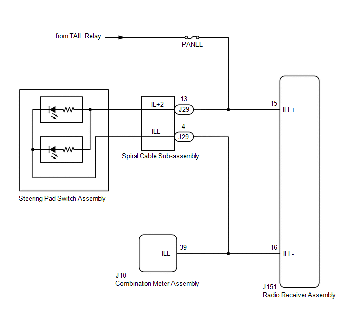
Power is supplied to the radio receiver assembly and steering pad switch assembly illumination when the light control switch is in the tail or head position.
WIRING DIAGRAM
CAUTION / NOTICE / HINT
NOTICE:
-
The vehicle is equipped with a Supplemental Restraint System (SRS) which includes components such as airbags. Before servicing (including removal or installation of parts), be sure to read the precaution for Supplemental Restraint System.
Click here
.gif)
- Inspect the fuses for circuits related to this system before performing the following procedure.
PROCEDURE
| 1. | CHECK ILLUMINATION |
(a) Check if the illumination for the radio receiver assembly, steering pad switch assembly, heater control switch or others (hazard switch, transmission control switch, etc.) comes on when the light control switch is turned to the head or tail position.
| Result | Proceed to |
|---|---|
| Illumination comes on for all components except steering pad switch assembly. | A |
| Illumination comes on for all components except radio receiver assembly. | B |
| No illumination comes on (radio receiver assembly, hazard switch, heater control switch, etc.). | C |
| B | .gif) | GO TO STEP 5 |
| C | | GO TO LIGHTING SYSTEM |
|
.gif)
| 2. | CHECK HARNESS AND CONNECTOR (ILLUMINATION SIGNAL) |
(a) Disconnect the J29 spiral cable sub-assembly connector.
(b) Measure the voltage according to the value(s) in the table below.
Standard Voltage:
| Tester Connection | Condition | Specified Condition |
|---|---|---|
| J29-13 (IL+2) - Body ground | Light control switch in tail or head position | 11 to 14 V |
| NG | | REPAIR OR REPLACE HARNESS OR CONNECTOR |
|
| 3. | INSPECT STEERING PAD SWITCH ASSEMBLY |
(a) Remove the steering pad switch assembly.
Click here
(b) Inspect the steering pad switch assembly.
Click here
| NG | | REPLACE STEERING PAD SWITCH ASSEMBLY |
|
| 4. | INSPECT SPIRAL CABLE SUB-ASSEMBLY |
(a) Remove the spiral cable sub-assembly.
Click here
(b) Inspect the spiral cable sub-assembly.
Click here
| OK | | REPAIR OR REPLACE HARNESS OR CONNECTOR (SPIRAL CABLE SUB-ASSEMBLY - RADIO RECEIVER ASSEMBLY, COMBINATION METER ASSEMBLY) |
| NG | | REPLACE SPIRAL CABLE SUB-ASSEMBLY |
| 5. | CHECK HARNESS AND CONNECTOR (ILLUMINATION SIGNAL) |
(a) Disconnect the J151 radio receiver assembly connector.
(b) Measure the voltage according to the value(s) in the table below.
Standard Voltage:
| Tester Connection | Condition | Specified Condition |
|---|---|---|
| J151-15 (ILL+) - Body ground | Light control switch in tail or head position | 11 to 14 V |
| NG | | REPAIR OR REPLACE HARNESS OR CONNECTOR |
|
| 6. | CHECK HARNESS AND CONNECTOR (RADIO RECEIVER ASSEMBLY - COMBINATION METER ASSEMBLY) |
(a) Disconnect the J151 radio receiver assembly connector.
(b) Disconnect the J10 combination meter assembly connector.
(c) Measure the resistance according to the value(s) in the table below.
Standard Resistance:
| Tester Connection | Condition | Specified Condition |
|---|---|---|
| J151-16 (ILL-) - J10-39 (ILL-) | Always | Below 1 Ω |
| J151-16 (ILL-) or J10-39 (ILL-) - Body ground | Always | 10 kΩ or higher |
| OK | | PROCEED TO NEXT SUSPECTED AREA SHOWN IN PROBLEM SYMPTOMS TABLE |
| NG | | REPAIR OR REPLACE HARNESS OR CONNECTOR |
 Steering Pad Switch Circuit
DESCRIPTION This circuit sends an operation signal from the steering pad switch assembly to the radio receiver assembly. If there is an open in the circuit, the audio system cannot be operated using t ...
 Speaker Circuit
DESCRIPTION If there is a short in a speaker circuit, the stereo component amplifier assembly detects it and stops output to the speakers. Thus sound cannot be heard from the speakers even if there is ...
Other materials:
Lexus RX (RX 350L, RX450h) 2016-2026 Repair Manual > Rear Light Assembly: Inspection
INSPECTION PROCEDURE 1. INSPECT REAR LIGHT ASSEMBLY LH (a) Apply battery voltage to the rear light assembly LH and check that the lights come on. OK: Condition Specified Condition Battery positive (+) → Terminal 2 (B) Battery negative (-) → Terminal 1 (E) Taillight comes on Ba ...
Lexus RX (RX 350L, RX450h) 2016-2026 Repair Manual > Vacuum Warning Switch: Installation
INSTALLATION PROCEDURE 1. INSTALL CHECK VALVE GROMMET (a) Install a new check valve grommet to the brake booster assembly. 2. INSTALL VACUUM WARNING SWITCH ASSEMBLY (for TMC Made) (a) Install the vacuum warning switch assembly to the brake booster assembly as shown in the illustration. *a 30° ...
Lexus RX (RX 350L, RX450h) 2016-{YEAR} Owners Manual
- For your information
- Pictorial index
- For safety and security
- Instrument cluster
- Operation of each component
- Driving
- Lexus Display Audio system
- Interior features
- Maintenance and care
- When trouble arises
- Vehicle specifications
- For owners
Lexus RX (RX 350L, RX450h) 2016-{YEAR} Repair Manual

0.0106