
Lexus RX (RX 350L, RX450h) 2016-2026 Repair Manual: Removal
REMOVAL
CAUTION / NOTICE / HINT
The necessary procedures (adjustment, calibration, initialization or registration) that must be performed after parts are removed and installed, or replaced during front seat assembly removal/installation are shown below.
Necessary Procedures After Parts Removed/Installed/Replaced| Replaced Part or Performed Procedure | Necessary Procedure | Effect/Inoperative Function when Necessary Procedure not Performed | Link |
|---|---|---|---|
|
*: When performing learning using the Techstream.
Click here | |||
| Disconnect cable from negative battery terminal | Memorize steering angle neutral point | Lane Control System | |
| Pre-collision System | |||
| Intelligent Clearance Sonar System* | |||
| Parking Assist Monitor System | | ||
| Panoramic View Monitor System | | ||
| Lighting System (w/ Automatic Headlight Beam Level Control System) | | ||
| Initialize back door lock | Power Door Lock Control System | | |
| Reset back door close position | Power Back Door System (w/ Outside Door Control Switch) | | |
| Zero point calibration (Occupant classification system) |
| |
| Initialize position control ECU | Front Power Seat Control System (w/ Memory) | |
CAUTION:
-
Be sure to read Precaution thoroughly before servicing.
Click here
.gif)
- Wear protective gloves. Sharp areas on the parts may injure your hands.
NOTICE:
for Standard Seat Type:- If the front seat airbag assembly was deployed, replace the front seat airbag assembly, front seatback frame sub-assembly, separate type front seatback pad and separate type front seatback cover with the necessary parts in accordance with the extent of the collision damage.
- If the front seat cushion airbag assembly RH was deployed, replace the front seat cushion airbag assembly RH, front seat adjuster assembly, separate type front seat cushion pad and separate type front seat cushion cover with the necessary parts in accordance with the extent of the collision damage.
- If the front seat airbag assembly was deployed, replace the front seat airbag assembly, front seatback frame sub-assembly and front seatback pad with cover with the necessary parts in accordance with the extent of the collision damage.
- If the front seat cushion airbag assembly RH was deployed, replace the front seat cushion airbag assembly RH, front seat adjuster assembly and front seat cushion pad with cover with the necessary parts in accordance with the extent of the collision damage.
HINT:
- Use the same procedure for the RH side and LH side.
- The following procedure is for the LH side.
PROCEDURE
1. PRECAUTION
NOTICE:
After turning the engine switch off, waiting time may be required before disconnecting the cable from the negative (-) battery terminal. Therefore, make sure to read the disconnecting the cable from the negative (-) battery terminal notices before proceeding with work.
Click here
2. REMOVE FRONT SEAT HEADREST ASSEMBLY
(a) Remove the front seat headrest assembly from the front seat assembly.
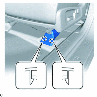
3. REMOVE FRONT OUTER SEAT TRACK BRACKET COVER
(a) Operate the slide and vertical power seat switch knob and move the front seat assembly to the rearmost position.
| (b) Disengage the 2 claws to remove the front outer seat track bracket cover. |
|
4. REMOVE FRONT INNER SEAT TRACK BRACKET COVER
| (a) Disengage the 2 claws to remove the front inner seat track bracket cover. |
|

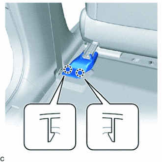
5. REMOVE REAR OUTER SEAT TRACK BRACKET COVER
(a) Operate the slide and vertical power seat switch knob and move the front seat assembly to the foremost position.
| (b) Disengage the 2 claws to remove the rear outer seat track bracket cover. |
|
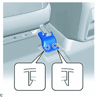
6. REMOVE REAR INNER SEAT TRACK BRACKET COVER
| (a) Disengage the 2 claws to remove the rear inner seat track bracket cover. |
|
7. REMOVE FRONT SEAT ASSEMBLY
| (a) Remove the 2 bolts on the rear side of the front seat assembly. |
|
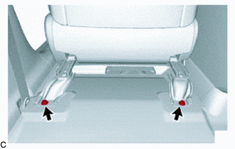
(b) Operate the slide and vertical power seat switch knob and move the front seat assembly to the rearmost position.
| (c) Remove the 2 bolts on the front side of the front seat assembly. |
|
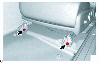
(d) Operate the slide and vertical power seat switch knob and move the front seat assembly to the center position.
(e) Operate the reclining power seat switch knob and move the seatback to the upright position.
(f) Operate the slide and vertical power seat switch knob and move the front seat assembly to the uppermost position.
(g) w/ Variable Seat Cushion System:
(1) Operate the seat variable cushion switch and raise the leg rest part of the seat cushion to the uppermost position.
(h) Disconnect the cable from the negative (-) battery terminal.
CAUTION:
Wait at least 90 seconds after disconnecting the cable from the negative (-) battery terminal to disable the SRS system.
NOTICE:
When disconnecting the cable, some systems need to be initialized after the cable is reconnected.
Click here
(i) Disconnect the front seat airbag assembly connector under the front seat assembly.
NOTICE:
When disconnecting any airbag connector, take care not to damage the airbag wire harness.
(1) Push down the white housing lock and slide the yellow CPA. (At this time, the connector cannot be disconnected yet.)
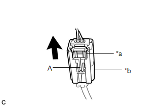
| *a | White Housing Lock |
| *b | Yellow CPA |
.png) | Slide |
(2) Push down the white housing lock again and disconnect the connector.
NOTICE:
Do not push down the part (A) shown in the illustration when disconnecting the connector.
(j) Disconnect each connector and disengage each clamp under the front seat assembly.
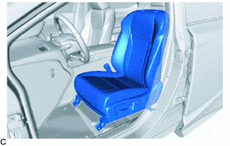
| (k) Remove the front seat assembly. NOTICE: Be careful not to damage the vehicle body. |
|
 Precaution
PRECAUTION HINT:
The following procedures are used to prevent wrinkles from forming when installing the seat cover. Make sure to follow the procedures correctly.
The shape of the seat shown i ...
 Disassembly
DISASSEMBLY CAUTION / NOTICE / HINT CAUTION: Wear protective gloves. Sharp areas on the parts may injure your hands. HINT:
Use the same procedure for the RH side and LH side.
The following proced ...
Other materials:
Lexus RX (RX 350L, RX450h) 2016-2026 Repair Manual > Dynamic Torque Control Awd System: Control Module Communication Bus Off (U0073)
DESCRIPTION The 4WD ECU assembly stores this DTC when a communication malfunction is detected. DTC No. Detection Item DTC Detection Condition Trouble Area U0073 Control Module Communication Bus Off
When the following continues for 5 seconds or more:
Signals from the 4WD ECU as ...
Lexus RX (RX 350L, RX450h) 2016-2026 Repair Manual > Power Tilt And Power Telescopic Steering Column System: Data List / Active Test
DATA LIST / ACTIVE TEST READ DATA LIST HINT: Using the Techstream to read the Data List allows the values or states of switches, sensors, actuators and other items to be read without removing any parts. This non-intrusive inspection can be very useful because intermittent conditions or signals may b ...
Lexus RX (RX 350L, RX450h) 2016-{YEAR} Owners Manual
- For your information
- Pictorial index
- For safety and security
- Instrument cluster
- Operation of each component
- Driving
- Lexus Display Audio system
- Interior features
- Maintenance and care
- When trouble arises
- Vehicle specifications
- For owners
Lexus RX (RX 350L, RX450h) 2016-{YEAR} Repair Manual

0.0104