Lexus RX (RX 350L, RX450h) 2016-2026 Repair Manual: Back Door Courtesy Switch Circuit
DESCRIPTION
The fold seat control ECU receives switch operation signals, the driving condition signal and back door courtesy light switch assembly signal and operates the rear power seat according to these signals.
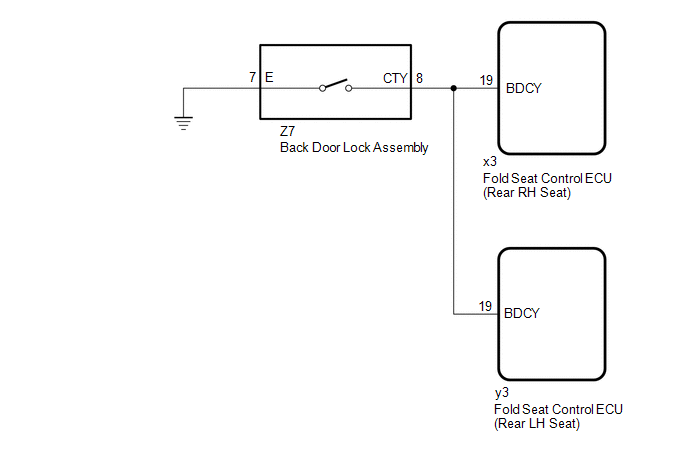
WIRING DIAGRAM
PROCEDURE
| 1. | CHECK BACK DOOR LOCK ASSEMBLY (BACK DOOR COURTESY LIGHT SWITCH) |
(a) Check that the back door lock assembly (back door courtesy light switch) turns on and off according to the back door operation.
OK:
Back door lock assembly (back door courtesy light switch) turns on and off normally according to the back door operation.
| NG | .gif) | GO TO LIGHTING SYSTEM |
|
.gif)
| 2. | CHECK HARNESS AND CONNECTOR (BACK DOOR LOCK ASSEMBLY - FOLD SEAT CONTROL ECU AND BODY GROUND) |
(a) Disconnect the Z7 back door lock assembly connector.
(b) Disconnect the x3*1 or y3*2 fold seat control ECU connector.
- *1: for Rear RH Seat
- *2: for Rear LH Seat
(c) Measure the resistance according to the value(s) in the table below.
Standard Resistance:
for Rear RH Seat
| Tester Connection | Condition | Specified Condition |
|---|---|---|
| Z7-8 (CTY) - x3-19 (BDCY) | Always | Below 1 Ω |
| Z7-7 (E) - Body ground | Always | Below 1 Ω |
| Z7-8 (CTY) or x3-19 (BDCY) - Body ground | Always | 10 kΩ or higher |
for Rear LH Seat
| Tester Connection | Condition | Specified Condition |
|---|---|---|
| Z7-8 (CTY) - y3-19 (BDCY) | Always | Below 1 Ω |
| Z7-7 (E) - Body ground | Always | Below 1 Ω |
| Z7-8 (CTY) or y3-19 (BDCY) - Body ground | Always | 10 kΩ or higher |
| OK | | GO TO PROBLEM SYMPTOMS TABLE |
| NG | | REPAIR OR REPLACE HARNESS OR CONNECTOR |
 Terminals Of Ecu
TERMINALS OF ECU CHECK FOLD SEAT CONTROL ECU RH (a) Disconnect the x3 and x4 fold seat control ECU RH connectors. (b) Measure the resistance and voltage according to the value(s) in the table below. ...
 Fold Seat Switch Circuit
DESCRIPTION When the fold seat switch assembly is operated, a switch operation signal is sent to the fold seat control ECU. According to the signal received, the fold seat control ECU operates the fol ...
Other materials:
Lexus RX (RX 350L, RX450h) 2016-2026 Repair Manual > Audio And Visual System (for 8 Inch Display): Dtc Check / Clear
DTC CHECK / CLEAR CHECK DTC (CHECK USING TECHSTREAM) (a) Connect the Techstream to the DLC3. (b) Turn the engine switch on (IG) and wait for 90 seconds. (c) Turn the Techstream on. (d) Enter the following menus: Body Electrical / Navigation System / Trouble Codes. Body Electrical > Navigation Sys ...
Lexus RX (RX 350L, RX450h) 2016-2026 Repair Manual > Brake Control / Dynamic Control Systems: Brake Pedal Load Sensing Switch
On-vehicle InspectionON-VEHICLE INSPECTION PROCEDURE 1. INSPECT BRAKE PEDAL SUPPORT ASSEMBLY (a) Make sure that there is no looseness in the locking part and the connecting part of the connector. *a Component without harness connected (Brake Pedal Load Sensing Switch (Brake Pedal S ...
Lexus RX (RX 350L, RX450h) 2016-{YEAR} Owners Manual
- For your information
- Pictorial index
- For safety and security
- Instrument cluster
- Operation of each component
- Driving
- Lexus Display Audio system
- Interior features
- Maintenance and care
- When trouble arises
- Vehicle specifications
- For owners
Lexus RX (RX 350L, RX450h) 2016-{YEAR} Repair Manual

0.01