Lexus RX (RX 350L, RX450h) 2016-2026 Repair Manual: Terminals Of Ecu
TERMINALS OF ECU
CHECK FOLD SEAT CONTROL ECU RH

(a) Disconnect the x3 and x4 fold seat control ECU RH connectors.
(b) Measure the resistance and voltage according to the value(s) in the table below.
| Terminal No. (Symbol) | Wiring Color | Terminal Description | Condition | Specified Condition |
|---|---|---|---|---|
| x3-1 (ECUB) - Body ground | W - Body ground | Battery power supply | Always | 11 to 14 V |
| x3-3 (IG) - Body ground | B - Body ground | IG power supply | Engine switch on (IG) | 11 to 14 V |
| Engine switch off | Below 1 V | |||
| x3-40 (IND2) - Body ground | W-B - Body ground | Ground | Always | Below 1 Ω |
| x4-1 (IND1) - Body ground | B - Body ground | Battery power supply | Always | 11 to 14 V |
| x4-2 (+B) - Body ground | W - Body ground | Battery power supply | Always | 11 to 14 V |
| x4-9 (GND2) - Body ground | W-B - Body ground | Ground | Always | Below 1 Ω |
| x4-10 (GND) - Body ground | W-B - Body ground | Ground | Always | Below 1 Ω |
(c) Reconnect the x3 and x4 fold seat control ECU RH connectors.
(d) Measure the resistance and voltage and check for pulses according to the value(s) in the table below.
| Terminal No. (Symbol) | Wiring Color | Terminal Description | Condition | Specified Condition |
|---|---|---|---|---|
| x3-7 (RCLR) - Body ground | SB - Body ground | Rear power seat switch RH (return switch) signal | Rear power seat switch RH off → on (return) | 11 to 14 V → Below 1 V |
| x3-8 (SG1) - Body ground | G - Body ground | Ground | Always | Below 1 Ω |
| x3-10 (SFLD) - x3-8 (SG1) | P - G | Fold motor position sensor signal | Motor operating | Pulse generation |
| x3-11 (SV1) - x3-8 (SG1) | R - G | Fold motor position sensor power supply | Engine switch off → on (IG) | Below 1 V → 5.5 to 8 V |
| x3-12 (RCLF) - Body ground | G - Body ground | Rear power seat switch RH (fold switch) signal | Rear power seat switch RH off → on (fold) | 11 to 14 V → Below 1 V |
| x3-17 (P) - Body ground | GR - Body ground | Driving condition signal |
| 11 to 14 V → Below 1 V |
| Engine switch off | 11 to 14 V | |||
| x3-18 (R CL) - Body ground | P - Body ground | Rear door courtesy light switch assembly RH signal | Rear door RH opened → closed | 11 to 14 V → Below 1 V |
| x3-19 (BDCY) - Body ground | R - Body ground | Back door courtesy light switch assembly signal | Back door opened → closed | 11 to 14 V → Below 1 V |
| x3-25 (RTRN) - Body ground | B - Body ground | Fold seat switch assembly (return switch) signal (for Rear Right Seat) | Fold seat switch assembly (for Rear Right Seat) off → on (return) | 11 to 14 V → Below 1 V |
| x3-26 (FOLD) - Body ground | L - Body ground | Fold seat switch assembly (fold switch) signal (for Rear Right Seat) | Fold seat switch assembly (for Rear Right Seat) off → on (fold) | 11 to 14 V → Below 1 V |
| x4-3 (RCL+) - Body ground | P - Body ground | Reclining motor operation signal | Rear power seat switch RH off → on (fold) | Below 1 V → 11 to 14 V |
| x4-4 (FLD+) - Body ground | L - Body ground | Fold motor operation signal | Rear power seat switch RH or Fold seat switch assembly (for Rear Right Seat) off → on (fold) | Below 1 V → 11 to 14 V |
| x4-7 (RCL-) - Body ground | LG - Body ground | Reclining motor operation signal | Rear power seat switch RH off → on (return) | Below 1 V → 11 to 14 V |
| x4-8 (FLD-) - Body ground | SB - Body ground | Return motor operation signal | Rear power seat switch RH or Fold seat switch assembly (for Rear Right Seat) off → on (return) | Below 1 V → 11 to 14 V |
CHECK FOLD SEAT CONTROL ECU LH
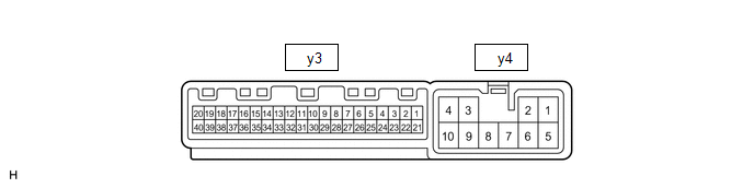
(a) Disconnect the y3 and y4 fold seat control ECU LH connectors.
(b) Measure the resistance and voltage according to the value(s) in the table below.
| Terminal No. (Symbol) | Wiring Color | Terminal Description | Condition | Specified Condition |
|---|---|---|---|---|
| y3-1 (ECUB) - Body ground | W - Body ground | Battery power supply | Engine switch on (IG) | 11 to 14 V |
| y3-3 (IG) - Body ground | B - Body ground | IG power supply | Engine switch on (IG) | 11 to 14 V |
| Engine switch off | Below 1 V | |||
| y3-40 (IND2) - Body ground | W-B - Body ground | Ground | Always | Below 1 Ω |
| y4-1 (IND1) - Body ground | B - Body ground | Battery power supply | Always | 11 to 14 V |
| y4-2 (+B) - Body ground | W - Body ground | Battery power supply | Always | 11 to 14 V |
| y4-9 (GND2) - Body ground | W-B - Body ground | Ground | Always | Below 1 Ω |
| y4-10 (GND) - Body ground | W-B - Body ground | Ground | Always | Below 1 Ω |
(c) Reconnect the y3 and y4 fold seat control ECU LH connectors.
(d) Measure the resistance and voltage and check for pulses according to the value(s) in the table below.
| Terminal No. (Symbol) | Wiring Color | Terminal Description | Condition | Specified Condition |
|---|---|---|---|---|
| y3-7 (RCLR) - Body ground | SB - Body ground | Rear power seat switch signal LH (return switch) signal | Rear power seat switch LH off → on (return) | 11 to 14 V → Below 1 V |
| y3-8 (SG1) - Body ground | G - Body ground | Ground | Always | Below 1 Ω |
| y3-10 (SFLD) - y3-8 (SG1) | P - G | Fold motor position sensor signal | Motor operating | Pulse generation |
| y3-11 (SV1) - y3-8 (SG1) | R - G | Fold motor position sensor power supply | Engine switch off → on (IG) | Below 1 V → 5.5 to 8 V |
| y3-12 (RCLF) - Body ground | G - Body ground | Rear power seat switch LH (fold switch) signal | Rear power seat switch LH off → on (fold) | 11 to 14 V → Below 1 V |
| y3-17 (P) - Body ground | GR - Body ground | Driving condition signal |
| 11 to 14 V → Below 1 V |
| Engine switch off | 11 to 14 V | |||
| y3-18 (R CL) - Body ground | P - Body ground | Rear door courtesy light switch assembly LH signal | Rear door LH opened → closed | 11 to 14 V → Below 1 V |
| y3-19 (BDCY) - Body ground | R - Body ground | Back door courtesy light switch assembly signal | Back door opened → closed | 11 to 14 V → Below 1 V |
| y3-25 (RTRN) - Body ground | B - Body ground | Fold seat switch assembly (fold switch) signal (for Rear Left Seat) | Fold seat switch assembly (for Rear Left Seat) off → on (return) | 11 to 14 V → Below 1 V |
| y3-26 (FOLD) - Body ground | L - Body ground | Fold seat switch assembly (fold switch) signal (for Rear Left Seat) | Fold seat switch assembly (for Rear Left Seat) off → on (fold) | 11 to 14 V → Below 1 V |
| y4-3 (RCL+) - Body ground | P - Body ground | Reclining motor operation signal | Rear power seat switch LH off → on (fold) | Below 1 V → 11 to 14 V |
| y4-4 (FLD+) - Body ground | L - Body ground | Fold motor operation signal | Rear power seat switch LH or Fold seat switch assembly (for Rear Left Seat) off → on (fold) | Below 1 V → 11 to 14 V |
| y4-7 (RCL-) - Body ground | LG - Body ground | Reclining motor operation signal | Rear power seat switch LH off → on (return) | Below 1 V → 11 to 14 V |
| y4-8 (FLD-) - Body ground | SB - Body ground | Return motor operation signal | Rear power seat switch LH or Fold seat switch assembly (for Rear Left Seat) off → on (return) | Below 1 V → 11 to 14 V |
 Operation Check
OPERATION CHECK CHECK BASIC FUNCTION HINT: The rear power seat switch is a collective term for the rear power seat switch RH and the rear power seat switch LH. (a) Operate the rear power seat switch, ...
 Back Door Courtesy Switch Circuit
DESCRIPTION The fold seat control ECU receives switch operation signals, the driving condition signal and back door courtesy light switch assembly signal and operates the rear power seat according to ...
Other materials:
Lexus RX (RX 350L, RX450h) 2016-2026 Repair Manual > Vehicle Stability Control System: Excessive Brake Pedal Travel (No Fluid Leaks and No Air in System)
CAUTION / NOTICE / HINT NOTICE: After replacing the skid control ECU (brake actuator assembly), perform "Calibration". Click here PROCEDURE 1. PRE-INSPECTION (a) Brake pedal inspection (1) Perform a visual inspection and operate the brake pedal to check for any malfunctions. (2) Check the ...
Lexus RX (RX 350L, RX450h) 2016-2026 Repair Manual > Navigation System: Data List / Active Test
DATA LIST / ACTIVE TEST DATA LIST NOTICE: In the table below, the values listed under "Normal Condition" are reference values. Do not depend solely on these reference values when deciding whether a part is faulty or not. HINT: Using the Techstream to read the Data List allows the values or states of ...
Lexus RX (RX 350L, RX450h) 2016-{YEAR} Owners Manual
- For your information
- Pictorial index
- For safety and security
- Instrument cluster
- Operation of each component
- Driving
- Lexus Display Audio system
- Interior features
- Maintenance and care
- When trouble arises
- Vehicle specifications
- For owners
Lexus RX (RX 350L, RX450h) 2016-{YEAR} Repair Manual

0.0122