Lexus RX (RX 350L, RX450h) 2016-2026 Repair Manual: Removal
REMOVAL
CAUTION / NOTICE / HINT
The necessary procedures (adjustment, calibration, initialization or registration) that must be performed after parts are removed and installed, or replaced during seat heater control removal/installation are shown below.
Necessary Procedure After Parts Removed/Installed/Replaced| Replaced Part or Performed Procedure | Necessary Procedures | Effect/Inoperative Function When Necessary Procedures are not Performed | Link |
|---|---|---|---|
| Disconnect cable from negative battery terminal | Memorize steering angle neutral point | Lane Control System | |
| Pre-collision System | |||
| Intelligent Clearance Sonar System*1 | |||
| Parking Assist Monitor System | | ||
| Panoramic View Monitor System | | ||
| Lighting System (w/ Automatic Headlight Beam Level Control System) | | ||
| Initialize back door lock | Power Door Lock Control System | | |
| Reset back door close position | Power Back Door System (w/ Outside Door Control Switch) | |
*1: When performing learning using the Techstream.
Click here .gif)
CAUTION:
-
Be sure to read Precaution thoroughly before servicing.
Click here
- Wear protective gloves. Sharp areas on the parts may injure your hands.
.png)
PROCEDURE
1. REMOVE REAR SEAT ASSEMBLY RH (w/o Rear No. 2 Seat)
for 60/40 Split Seat Type RH Side:
Click here
2. REMOVE SEAT HEATER CONTROL SUB-ASSEMBLY (w/o Rear No. 2 Seat)
(a) for 60/40 Split Seat Type RH Side:
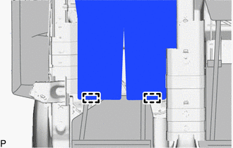
| (1) Disengage the 2 hooks to disconnect the separate type rear seat cushion cover with pad. |
|
.png)
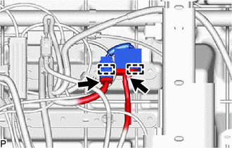
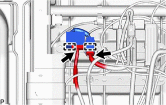
| (2) Disconnect the 2 connectors. |
|
.png)
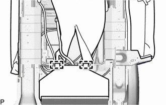
(3) Disengage the 2 clamps to remove the seat heater control sub-assembly.
3. REMOVE REAR SEAT ASSEMBLY LH (w/o Rear No. 2 Seat)
for 60/40 Split Seat Type LH Side:
Click here
4. REMOVE SEAT HEATER CONTROL SUB-ASSEMBLY (w/o Rear No. 2 Seat)
(a) for 60/40 Split Seat Type LH Side:
| (1) Disengage the 2 hooks to disconnect the separate type rear seat cushion cover with pad. |
|
.png)
| (2) Disconnect the 2 connectors. |
|
.png)
(3) Disengage the 2 clamps to remove the seat heater control sub-assembly.
5. REMOVE REAR NO. 1 SEAT ASSEMBLY RH (w/ Rear No. 2 Seat)
for 60/40 Split Seat Type RH Side:
Click here
for Captain Seat Type:
HINT:
Use the same procedure as for the LH side.
6. REMOVE SEAT HEATER CONTROL SUB-ASSEMBLY RH (w/ Rear No. 2 Seat)
(a) for 60/40 Split Seat Type RH Side:
| (1) Disengage the 2 hooks to disconnect the separate type rear seat cushion cover with pad. |
|
| (2) Disconnect the 2 connectors. |
|
(3) Disengage the 2 clamps to remove the seat heater control sub-assembly RH.
(b) for Captain Seat Type:
HINT:
Use the same procedure as for the LH side.
7. REMOVE REAR NO. 1 SEAT ASSEMBLY LH (w/ Rear No. 2 Seat)
for 60/40 Split Seat Type LH Side:
Click here
for Captain Seat Type:
Click here
8. REMOVE SEAT HEATER CONTROL SUB-ASSEMBLY LH (w/ Rear No. 2 Seat)
(a) for 60/40 Split Seat Type LH Side or Captain Seat Type:
| (1) Disengage the 2 hooks to disconnect the separate type rear seat cushion cover with pad. |
|
| (2) Disconnect the 2 connectors. |
|
(3) Disengage the 2 clamps to remove the seat heater control sub-assembly LH.
 Installation
INSTALLATION CAUTION / NOTICE / HINT CAUTION: Wear protective gloves. Sharp areas on the seat frame may injure your hands. PROCEDURE 1. INSTALL SEAT HEATER CONTROL SUB-ASSEMBLY (w/o Rear No. 2 Seat) ( ...

Other materials:
Lexus RX (RX 350L, RX450h) 2016-2026 Repair Manual > Glove Box Light: Installation
INSTALLATION PROCEDURE 1. INSTALL GLOVE BOX LIGHT ASSEMBLY (a) Turn the glove box light assembly as shown in the illustration to install it. Install in this Direction 2. INSTALL GLOVE COMPARTMENT DOOR ASSEMBLY Click here 3. INSTALL LOWER NO. 1 INSTRUMENT PANEL FINISH PANEL Click here ...
Lexus RX (RX 350L, RX450h) 2016-2026 Repair Manual > Dynamic Radar Cruise Control System: Road Test
ROAD TEST HINT:
The dynamic radar cruise control system has 2 cruise control modes: constant speed control mode and vehicle-to-vehicle distance control mode.
Vehicle-to-vehicle distance control mode is selected by default when the dynamic radar cruise control system is turned on using the cruis ...
Lexus RX (RX 350L, RX450h) 2016-{YEAR} Owners Manual
- For your information
- Pictorial index
- For safety and security
- Instrument cluster
- Operation of each component
- Driving
- Lexus Display Audio system
- Interior features
- Maintenance and care
- When trouble arises
- Vehicle specifications
- For owners
Lexus RX (RX 350L, RX450h) 2016-{YEAR} Repair Manual

0.0089