Lexus RX (RX 350L, RX450h) 2016-2026 Repair Manual: Terminals Of Ecu
TERMINALS OF ECU
CHECK AIR CONDITIONING AMPLIFIER ASSEMBLY
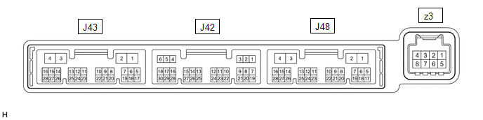
(a) Disconnect the J43 air conditioning amplifier assembly connector.
(b) Measure the voltage and resistance according to the value(s) in the table below.
HINT:
Measure the values on the wire harness side with the connector disconnected.
| Terminal No. (Symbol) | Wiring Color | Terminal Description | Condition | Specified Condition |
|---|---|---|---|---|
| J43-2 (IG+) - Body ground | GR - Body ground | IG power supply | Engine switch on (IG) | 11 to 14 V |
| J43-2 (IG+) - Body ground | GR - Body ground | IG power supply | Engine switch off | Below 1 V |
| J43-4 (GND) - Body ground | W-B - Body ground | Ground | Always | Below 1 Ω |
| J48-1 (GND2) - Body ground* | W-B - Body ground | Ground | Always | Below 1 Ω |
- *: w/ Rear No. 2 Seat
(c) Reconnect the J43 air conditioning amplifier assembly connector.
(d) Measure the voltage and check for pulse generation according to the value(s) in the table below.
| Terminal No. (Symbol) | Wiring Color | Terminal Description | Condition | Specified Condition |
|---|---|---|---|---|
| J48-16 (SHP+) - J43-4 (GND) | Y - W-B | Refreshing seat switch volume signal |
| Below 1 V |
| J48-15 (SHD+) - J43-4 (GND) | P - W-B | Refreshing seat switch volume signal |
| Below 1 V |
| J43-14 (LIN1) - Body ground | G - Body ground | Refreshing seat switch signal | Engine switch on (IG) | Pulse generation |
CHECK REFRESHING SEAT SWITCH (FOR FRONT SIDE)

(a) Disconnect the J82 refreshing seat switch connector.
(b) Measure the voltage and resistance according to the value(s) in the table below.
HINT:
Measure the values on the wire harness side with the connector disconnected.
| Terminal No. (Symbol) | Wiring Color | Terminal Description | Condition | Specified Condition |
|---|---|---|---|---|
| J82-2 (IG) - Body ground | L - Body ground | IG power supply | Engine switch on (IG) | 11 to 14 V |
| J82-2 (IG) - Body ground | L- Body ground | IG power supply | Engine switch off | Below 1 V |
| J82-7 (E) - Body ground | W-B - Body ground | Ground | Always | Below 1 Ω |
(c) Reconnect the J82 refreshing seat switch connector.
(d) Check for pulse according to the value(s) in the table below.
| Terminal No. (Symbol) | Wiring Color | Terminal Description | Condition | Specified Condition |
|---|---|---|---|---|
| J82-4 (LIN1) - Body ground | G - Body ground | Refreshing seat switch signal | Engine switch on (IG) | Pulse generation |
CHECK REFRESHING SEAT SWITCH (FOR REAR SIDE) (w/ Rear Seat Heater) (w/o Rear No. 2 Seat)

(a) Disconnect the J15 refreshing seat switch connector.
(b) Measure the voltage and resistance according to the value(s) in the table below.
HINT:
Measure the values on the wire harness side with the connector disconnected.
| Terminal No. (Symbol) | Wiring Color | Terminal Description | Condition | Specified Condition |
|---|---|---|---|---|
| J15-1 (IG) - Body ground | LG - Body ground | IG power supply | Engine switch on (IG) | 11 to 14 V |
| J15-1 (IG) - Body ground | LG - Body ground | IG power supply | Engine switch off | Below 1 V |
| J15-5 (E) - Body ground | W-B - Body ground | Ground | Always | Below 1 Ω |
(c) Reconnect the J15 refreshing seat switch connector.
(d) Check for pulse according to the value(s) in the table below.
| Terminal No. (Symbol) | Wiring Color | Terminal Description | Condition | Specified Condition |
|---|---|---|---|---|
| J15-3 (RLIN) - Body ground | R - Body ground | Refreshing seat switch signal | Engine switch on (IG) | Pulse generation |
CHECK REAR SEAT HEATER SWITCH (w/ Rear Seat Heater) (w/ Rear No. 2 Seat)

(a) Disconnect the V4 rear seat heater switch connector.
(b) Measure the voltage and resistance according to the value(s) in the table below.
HINT:
Measure the values on the wire harness side with the connector disconnected.
| Terminal No. (Symbol) | Wiring Color | Terminal Description | Condition | Specified Condition |
|---|---|---|---|---|
| V4-1 (IG) - Body ground | LG - Body ground | IG power supply | Engine switch on (IG) | 11 to 14 V |
| V4-1 (IG) - Body ground | LG - Body ground | IG power supply | Engine switch off | Below 1 V |
| V4-5 (E) - Body ground | W-B - Body ground | Ground | Always | Below 1 Ω |
(c) Reconnect the V4 rear seat heater switch connector.
(d) Check for pulse according to the value(s) in the table below.
| Terminal No. (Symbol) | Wiring Color | Terminal Description | Condition | Specified Condition |
|---|---|---|---|---|
| V4-3 (RLIN) - Body ground | R - Body ground | Rear seat heater switch signal | Engine switch on (IG) | Pulse generation |
 Diagnosis System
DIAGNOSIS SYSTEM DESCRIPTION (a) Seat heater system data and Diagnostic Trouble Codes (DTCs) can be read through the Data Link Connector 3 (DLC3) of the vehicle. When the system seems to be malfunctio ...
 Dtc Check / Clear
DTC CHECK / CLEAR CHECK DTC (a) Connect the Techstream to the DLC3. (b) Turn the engine switch on (IG). (c) Turn the Techstream on. (d) Enter the following menus: Body Electrical / Air Conditioner / T ...
Other materials:
Lexus RX (RX 350L, RX450h) 2016-2026 Repair Manual > Lighting System (w/o Automatic Headlight Beam Level Control System): LED Headlight LH (B2430,B2431)
DESCRIPTION These DTCs are stored when the low beam headlights do not illuminate, or a communication malfunction is detected between the headlight assembly and main body ECU (multiplex network body ECU). DTC No. Detection Item DTC Detection Condition Trouble Area DTC Output from B2430 ...
Lexus RX (RX 350L, RX450h) 2016-2026 Owners Manual > Basic Operations: Lexus Display Audio
system
Use the following buttons to start listening to the audio system.
Lexus Display Audio operation buttons
Disc slot
"TUNE*SCROLL" knob
Select a radio station band, track or file.
Except radio and A/V mode: Pause or resume playing a track or file.
Radio and A/V mode: Turn mute on/off.
...
Lexus RX (RX 350L, RX450h) 2016-{YEAR} Owners Manual
- For your information
- Pictorial index
- For safety and security
- Instrument cluster
- Operation of each component
- Driving
- Lexus Display Audio system
- Interior features
- Maintenance and care
- When trouble arises
- Vehicle specifications
- For owners
Lexus RX (RX 350L, RX450h) 2016-{YEAR} Repair Manual

0.011