Lexus RX (RX 350L, RX450h) 2016-2026 Repair Manual: LED Headlight LH (B2430,B2431)
DESCRIPTION
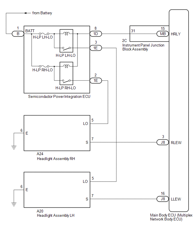
These DTCs are stored when the low beam headlights do not illuminate, or a communication malfunction is detected between the headlight assembly and main body ECU (multiplex network body ECU).
| DTC No. | Detection Item | DTC Detection Condition | Trouble Area | DTC Output from |
|---|---|---|---|---|
| B2430 | LED Headlight LH |
|
| Main Body |
| B2431 | LED Headlight RH |
|
| Main Body |
WIRING DIAGRAM
CAUTION / NOTICE / HINT
NOTICE:
- Inspect the fuses for circuits related to this system before performing the following inspection procedure.
-
Before replacing the main body ECU (multiplex network body ECU), refer to Registration.
Click here
.gif)
PROCEDURE
| 1. | CLEAR DTC |
(a) Connect the Techstream to the DLC3.
(b) Turn the engine switch on (IG).
(c) Turn the Techstream on.
(d) Enter the following menus: Body Electrical / Main Body / Trouble Codes.
(e) Clear the DTCs.
Body Electrical > Main Body > Clear DTCs
|
.gif)
| 2. | CHECK FOR DTC |
(a) Connect the Techstream to the DLC3.
(b) Start the engine.
(c) Operate the light control switch to turn on the low beam headlights and wait 12 seconds or more.
(d) Turn the Techstream on.
(e) Enter the following menus: Body Electrical / Main Body / Trouble Codes.
(f) Check for DTCs.
Body Electrical > Main Body > Trouble CodesOK:
DTC B2430 and B2431 are not output.
| Result | Proceed to |
|---|---|
| Both DTC B2430 and B2431 are not output | A |
| Both DTC B2430 and B2431 are output | B |
| Only DTC B2430 or B2431 is output | C |
| A | .gif) | USE SIMULATION METHOD TO CHECK |
| C | | GO TO STEP 7 |
|
| 3. | INSPECT SEMICONDUCTOR POWER INTEGRATION ECU |
(a) Remove the semiconductor power integration ECU from the engine room relay block and junction block assembly.
Click here
(b) Inspect the semiconductor power integration ECU.
Click here
OK:
Semiconductor power integration ECU is normal.
| NG | | REPLACE SEMICONDUCTOR POWER INTEGRATION ECU |
|
| 4. | CHECK HARNESS AND CONNECTOR (POWER SOURCE - SEMICONDUCTOR POWER INTEGRATION ECU) |
(a) Measure the voltage according to the value(s) in the table below.
Standard Voltage:
| Tester Connection | Condition | Specified Condition |
|---|---|---|
| B-1 (BATT) - Body ground | Always | 11 to 14 V |
| NG | | REPAIR OR REPLACE HARNESS OR CONNECTOR |
|
| 5. | CHECK HARNESS AND CONNECTOR (SEMICONDUCTOR POWER INTEGRATION ECU - INSTRUMENT PANEL JUNCTION BLOCK ASSEMBLY) |
(a) Disconnect the 2C instrument panel junction block assembly connector.
(b) Measure the resistance according to the value(s) in the table below.
Standard Resistance:
| Tester Connection | Condition | Specified Condition |
|---|---|---|
| 1D-8 - 2C-31 | Always | Below 1 Ω |
| 1D-8 or 2C-31 - Body ground | Always | 10 kΩ or higher |
| NG | | REPAIR OR REPLACE HARNESS OR CONNECTOR |
|
| 6. | INSPECT INSTRUMENT PANEL JUNCTION BLOCK ASSEMBLY |
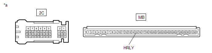
| *a | Component without harness connected (Instrument Panel Junction Block Assembly) | - | - |
(a) Remove the main body ECU (multiplex network body ECU) from the instrument panel junction block assembly.
Click here
(b) Measure the resistance according to the value(s) in the table below.
Standard Resistance:
| Tester Connection | Condition | Specified Condition |
|---|---|---|
| 2C-31 - MB-15 (HRLY) | Always | Below 1 Ω |
| OK | | REPLACE MAIN BODY ECU (MULTIPLEX NETWORK BODY ECU) |
| NG | | REPLACE INSTRUMENT PANEL JUNCTION BLOCK ASSEMBLY |
| 7. | INSPECT SEMICONDUCTOR POWER INTEGRATION ECU |
(a) Remove the semiconductor power integration ECU from the engine room relay block and junction block assembly.
Click here
(b) Inspect the semiconductor power integration ECU.
Click here
OK:
Semiconductor power integration ECU is normal.
| NG | | REPLACE SEMICONDUCTOR POWER INTEGRATION ECU |
|
| 8. | CHECK HARNESS AND CONNECTOR (HEADLIGHT ASSEMBLY LO TERMINAL VOLTAGE) |
| (a) Disconnect the A20 headlight assembly LH connector. |
|
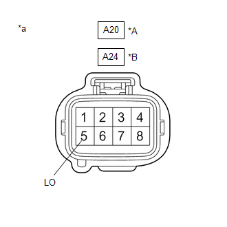
(b) Disconnect the A24 headlight assembly RH connector.
(c) Measure the voltage according to the value(s) in the table below.
Standard Voltage:
for LH Side| Tester Connection | Condition | Specified Condition |
|---|---|---|
| A20-5 (LO) - Body ground | Light control switch in head position | 11 to 14 V |
| Tester Connection | Condition | Specified Condition |
|---|---|---|
| A24-5 (LO) - Body ground | Light control switch in head position | 11 to 14 V |
| NG | | REPAIR OR REPLACE HARNESS OR CONNECTOR |
|
| 9. | CHECK HARNESS AND CONNECTOR (HEADLIGHT ASSEMBLY - BODY GROUND) |
(a) Measure the resistance according to the value(s) in the table below.
Standard Resistance:
for LH Side| Tester Connection | Condition | Specified Condition |
|---|---|---|
| A20-6 (E) - Body ground | Always | Below 1 Ω |
| Tester Connection | Condition | Specified Condition |
|---|---|---|
| A24-6 (E) - Body ground | Always | Below 1 Ω |
| NG | | REPAIR OR REPLACE HARNESS OR CONNECTOR |
|
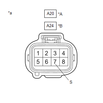
| 10. | CHECK HARNESS AND CONNECTOR (HEADLIGHT ASSEMBLY S TERMINAL VOLTAGE) |
| (a) Measure the voltage according to the value(s) in the table below. Standard Voltage: for LH Side
|
|
| Result | Proceed to |
|---|---|
| OK (for TMC Made) | A |
| OK (for TMMC Made) | B |
| NG | C |
| A | | REPLACE HEADLIGHT UNIT |
| B | | REPLACE HEADLIGHT ASSEMBLY |
|
| 11. | CHECK HARNESS AND CONNECTOR (HEADLIGHT ASSEMBLY - MAIN BODY ECU (MULTIPLEX NETWORK BODY ECU)) |
(a) Disconnect the J8 main body ECU (multiplex network body ECU) connector.
(b) Measure the voltage according to the value(s) in the table below.
Standard Voltage:
for LH Side| Tester Connection | Condition | Specified Condition |
|---|---|---|
| A20-7 (S) - J8-16 (LLEW) | Always | Below 1 Ω |
| A20-7 (S) or J8-16 (LLEW) - Body ground | Always | 10 kΩ or higher |
| Tester Connection | Condition | Specified Condition |
|---|---|---|
| A24-7 (S) - J8-3 (RLEW) | Always | Below 1 Ω |
| A24-7 (S) or J8-3 (RLEW) - Body ground | Always | 10 kΩ or higher |
| OK | | REPLACE MAIN BODY ECU (MULTIPLEX NETWORK BODY ECU) |
| NG | | REPAIR OR REPLACE HARNESS OR CONNECTOR |
 Automatic High Beam Camera (B124C)
DESCRIPTION The main body ECU (multiplex network body ECU) detects a high beam headlight illumination request signal of the automatic high beam system from the forward recognition camera. DTC No. ...
 Lost Communication With ECM/PCM "A" Missing Message (U010087,U012587,U012987,U014087)
DESCRIPTION These DTCs are stored if a CAN communication malfunction occurs between the forward recognition camera and other ECUs. DTC No. Detection Item DTC Detection Condition Trouble Area ...
Other materials:
Lexus RX (RX 350L, RX450h) 2016-2026 Repair Manual > Airbag System: Short in Side Squib (RH) Circuit (B1820-B1823)
DESCRIPTION The front side squib RH circuit consists of the airbag sensor assembly and front seat airbag assembly RH. The airbag sensor assembly uses this circuit to deploy the airbag when deployment conditions are met. These DTCs are stored when a malfunction is detected in the front side squib RH ...
Lexus RX (RX 350L, RX450h) 2016-2026 Repair Manual > Knee Airbag Assembly: Removal
REMOVAL CAUTION / NOTICE / HINT The necessary procedures (adjustment, calibration, initialization, or registration) that must be performed after parts are removed, installed, or replaced during the lower No. 1 instrument panel airbag assembly removal/installation are shown below. Necessary Procedure ...
Lexus RX (RX 350L, RX450h) 2016-{YEAR} Owners Manual
- For your information
- Pictorial index
- For safety and security
- Instrument cluster
- Operation of each component
- Driving
- Lexus Display Audio system
- Interior features
- Maintenance and care
- When trouble arises
- Vehicle specifications
- For owners
Lexus RX (RX 350L, RX450h) 2016-{YEAR} Repair Manual

0.0133