Lexus RX (RX 350L, RX450h) 2016-2026 Repair Manual: Start Up Signal Circuit between Radio Receiver Assembly and Navigation ECU
DESCRIPTION
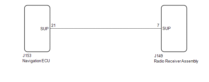
This circuit includes the navigation ECU and radio receiver assembly.
WIRING DIAGRAM
PROCEDURE
| 1. | CHECK HARNESS AND CONNECTOR (RADIO RECEIVER ASSEMBLY - NAVIGATION ECU) |
(a) Disconnect the J149 radio receiver assembly connector.
(b) Disconnect the J153 navigation ECU connector.
(c) Measure the resistance according to the value(s) in the table below.
Standard Resistance:
| Tester Connection | Condition | Specified Condition |
|---|---|---|
| J149-7 (SUP) - J153-21 (SUP) | Always | Below 1 Ω |
| J149-7 (SUP) or J153-21 (SUP) - Body ground | Always | 10 kΩ or higher |
| OK |  | PROCEED TO NEXT SUSPECTED AREA SHOWN IN PROBLEM SYMPTOMS TABLE |
| NG | | REPAIR OR REPLACE HARNESS OR CONNECTOR |
 Reverse Signal Circuit between Radio Receiver Assembly and Navigation ECU
DESCRIPTION This circuit includes the navigation ECU and radio receiver assembly. WIRING DIAGRAM PROCEDURE 1. CHECK HARNESS AND CONNECTOR (RADIO RECEIVER ASSEMBLY - NAVIGATION ECU) (a) Disco ...
 Microphone Circuit
DESCRIPTION
The radio receiver assembly and telephone microphone assembly are connected to each other using the microphone connection detection signal lines.
Using this circuit, the DCM (telemati ...
Other materials:
Lexus RX (RX 350L, RX450h) 2016-2026 Repair Manual > Rear Center Seat Outer Belt Assembly(w/o Rear No. 2 Seat): Installation
INSTALLATION PROCEDURE 1. INSTALL REAR CENTER SEAT OUTER BELT ASSEMBLY (a) Install the rear center seat outer belt assembly with the 2 nuts. Torque: Nut (A) : 12.5 N·m {127 kgf·cm, 9 ft·lbf} Nut (B) : 42 N·m {428 kgf·cm, 31 ft·lbf} 2. INSTALL SEATBACK FELT RH (for TMK Made) Click here 3. ...
Lexus RX (RX 350L, RX450h) 2016-2026 Repair Manual > Audio And Visual System (for 8 Inch Display): Touch Panel Switch does not Function
CAUTION / NOTICE / HINT NOTICE: Depending on the parts that are replaced during vehicle inspection or maintenance, performing initialization, registration or calibration may be needed. Refer to Precaution for Audio and Visual System. Click here PROCEDURE 1. CHECK MULTI-DISPLAY (a) Check i ...
Lexus RX (RX 350L, RX450h) 2016-{YEAR} Owners Manual
- For your information
- Pictorial index
- For safety and security
- Instrument cluster
- Operation of each component
- Driving
- Lexus Display Audio system
- Interior features
- Maintenance and care
- When trouble arises
- Vehicle specifications
- For owners
Lexus RX (RX 350L, RX450h) 2016-{YEAR} Repair Manual

0.0135