Lexus RX (RX 350L, RX450h) 2016-2026 Repair Manual: Removal
REMOVAL
CAUTION / NOTICE / HINT
The necessary procedures (adjustment, calibration, initialization or registration) that must be performed after parts are removed and installed, or replaced during seat variable cushion switch removal/installation are shown below.
Necessary Procedures After Parts Removed/Installed/Replaced| Replaced Part or Performed Procedure | Necessary Procedure | Effect/Inoperative Function when Necessary Procedure not Performed | Link |
|---|---|---|---|
|
*: When performing learning using the Techstream.
Click here | |||
| Disconnect cable from negative battery terminal | Memorize steering angle neutral point | Lane Control System | |
| Pre-collision System | |||
| Intelligent Clearance Sonar System* | |||
| Parking Assist Monitor System | | ||
| Panoramic View Monitor System | | ||
| Lighting System (w/ Automatic Headlight Beam Level Control System) | | ||
| Initialize back door lock | Power Door Lock Control System | | |
| Reset back door close position | Power Back Door System (w/ Outside Door Control Switch) | | |
CAUTION:
Wear protective gloves. Sharp areas on the parts may injure your hands.
HINT:
- Use the same procedure for the RH side and LH side.
- The following procedure is for the LH side.
PROCEDURE
1. REMOVE FRONT SEAT ASSEMBLY
Click here .gif)
2. DISCONNECT FRONT SEATBACK BOARD SUB-ASSEMBLY
Click here
3. REMOVE FRONT SEAT CUSHION SHIELD
Click here
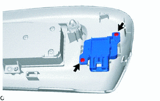
4. REMOVE SEAT VARIABLE CUSHION SWITCH
| (a) Remove the 2 screws and seat variable cushion switch from the front seat cushion shield. |
|
 Components
COMPONENTS ILLUSTRATION *1 FRONT SEAT CUSHION SHIELD - - ILLUSTRATION *1 FRONT SEAT CUSHION SHIELD *2 SEAT VARIABLE CUSHION SWITCH ...
 Installation
INSTALLATION CAUTION / NOTICE / HINT CAUTION: Wear protective gloves. Sharp areas on the parts may injure your hands. HINT:
Use the same procedure for the RH side and LH side.
The following proce ...
Other materials:
Lexus RX (RX 350L, RX450h) 2016-2026 Repair Manual > Headlight Ecu: Removal
REMOVAL CAUTION / NOTICE / HINT The necessary procedures (adjustment, calibration, initialization or registration) that must be performed after parts are removed and installed, or replaced during No. 1 headlight ECU sub-assembly removal/installation are shown below. Necessary Procedure After Parts R ...
Lexus RX (RX 350L, RX450h) 2016-2026 Repair Manual > Meter / Gauge System: Precaution
PRECAUTION PRECAUTION FOR DISCONNECTING CABLE FROM NEGATIVE BATTERY TERMINAL NOTICE: When disconnecting the cable from the negative (-) battery terminal, initialize the following systems after the cable is reconnected. System Name See Procedure Lane Control System Pre-collision Sys ...
Lexus RX (RX 350L, RX450h) 2016-{YEAR} Owners Manual
- For your information
- Pictorial index
- For safety and security
- Instrument cluster
- Operation of each component
- Driving
- Lexus Display Audio system
- Interior features
- Maintenance and care
- When trouble arises
- Vehicle specifications
- For owners
Lexus RX (RX 350L, RX450h) 2016-{YEAR} Repair Manual

0.0113