Lexus RX (RX 350L, RX450h) 2016-2026 Repair Manual: Removal
REMOVAL
CAUTION / NOTICE / HINT
The necessary procedures (adjustment, calibration, initialization or registration) that must be performed after parts are removed and installed, or replaced during No. 1 headlight ECU sub-assembly removal/installation are shown below.
Necessary Procedure After Parts Removed/Installed/Replaced| Replaced Part or Performed Procedure | Necessary Procedure | Effect/Inoperative Function when Necessary Procedure not Performed | Link |
|---|---|---|---|
| Front bumper assembly | Front television camera view adjustment | Panoramic view monitor system | |
| Front bumper assembly (w/ Intelligent clearance sonar system) |
|
| |
| No. 1 headlight ECU sub-assembly LH |
| Lighting System (w/ Automatic Headlight Beam Level Control System) | |
NOTICE:
If the No. 1 headlight ECU sub-assembly RH is replaced with a new one, vehicle information registration and initialization are not necessary.
HINT:
- Use the same procedure for the RH side and LH side.
- The following procedure is for the LH side.
PROCEDURE
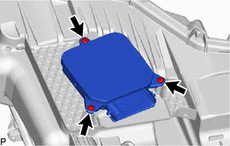
1. REMOVE HEADLIGHT ASSEMBLY
Click here .gif)
2. REMOVE NO. 1 HEADLIGHT ECU SUB-ASSEMBLY
NOTICE:
- Make sure to replace the headlight gasket with a new one. Failure to do so may cause water ingress.
- If the No. 1 headlight ECU sub-assembly has been struck or dropped, replace it with a new one.
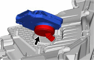
| (a) Remove the 3 screws. |
|
| (b) Separate the connector cover from the No. 1 headlight ECU sub-assembly. |
|
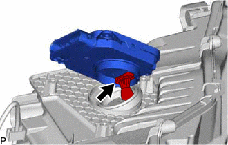
(c) for Single Beam Headlight:
| (1) Disconnect the connector to remove the No. 1 headlight ECU sub-assembly. |
|
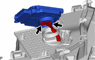
(d) except Single Beam Headlight:
| (1) Disconnect the 2 connectors to remove the No. 1 headlight ECU sub-assembly. |
|
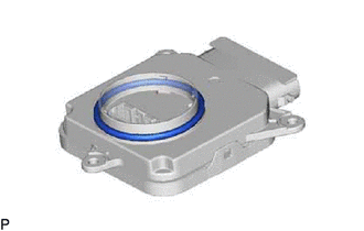
3. REMOVE HEADLIGHT GASKET
NOTICE:
Make sure to replace the headlight gasket with a new one. Failure to do so may cause water ingress.
| (a) Remove the headlight gasket. |
|
 Installation
INSTALLATION CAUTION / NOTICE / HINT HINT:
Use the same procedure for the RH side and LH side.
The following procedure is for the LH side.
PROCEDURE 1. INSTALL HEADLIGHT GASKET (a) Install a n ...

Other materials:
Lexus RX (RX 350L, RX450h) 2016-2026 Repair Manual > Can Communication System: Check Bus 3 Lines for Short Circuit
DESCRIPTION There may be a short circuit between the bus 3 main lines and/or bus 3 branch lines when the resistance between terminals 6 (CA3H) and 21 (CA3L) of the network gateway ECU is below 54 Ω. Symptom Trouble Area Resistance between terminals 6 (CA3H) and 21 (CA3L) of network gateway ...
Lexus RX (RX 350L, RX450h) 2016-2026 Repair Manual > Vacuum Switching Valve (for Engine Mounting): Removal
REMOVAL PROCEDURE 1. REMOVE COOL AIR INTAKE DUCT SEAL Click here 2. REMOVE INLET AIR CLEANER ASSEMBLY (a) Remove the 2 bolts and inlet air cleaner assembly from the air cleaner case sub-assembly. 3. REMOVE NO. 2 VACUUM SWITCHING VALVE ASSEMBLY (a) Disconnect the 2 vacuum hoses ...
Lexus RX (RX 350L, RX450h) 2016-{YEAR} Owners Manual
- For your information
- Pictorial index
- For safety and security
- Instrument cluster
- Operation of each component
- Driving
- Lexus Display Audio system
- Interior features
- Maintenance and care
- When trouble arises
- Vehicle specifications
- For owners
Lexus RX (RX 350L, RX450h) 2016-{YEAR} Repair Manual

0.0088