Lexus RX (RX 350L, RX450h) 2016-2026 Repair Manual: Removal
REMOVAL
CAUTION / NOTICE / HINT
The necessary procedures (adjustment, calibration, initialization, or registration) that must be performed after parts are removed and installed, or replaced during rear air conditioning unit removal/installation are shown below.
Necessary Procedure After Parts Removed/Installed/Replaced| Replaced Part or Performed Procedure | Necessary Procedure | Effect/Inoperative Function when Necessary Procedure not Performed | Link |
|---|---|---|---|
| Initialization servo motor (Air conditioning system) | DTCs are output | |
PROCEDURE
1. PRECAUTION
NOTICE:
- Make sure to select foot mode before removing the rear cooling unit assembly.
- Make sure to perform initialization after replacing the cooling unit damper servo sub-assembly. If initialization is not performed, the rear air conditioning unit will not perform properly as the air conditioning amplifier assembly will not be able to recognize the position of the cooling unit damper servo sub-assembly.
2. RECOVER REFRIGERANT FROM REFRIGERATION SYSTEM
Click here .gif)
3. DRAIN ENGINE COOLANT
Click here
4. REMOVE NO. 1 LUGGAGE COMPARTMENT SIDE COVER PROTECTOR
(a) Remove the 2 screws and grommet.
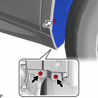
.png) | Screw |
.png) | Grommet |
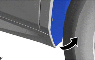
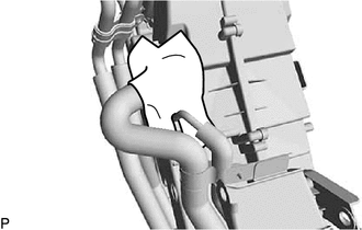
| (b) Turn back the rear wheel house liner RH as shown in the illustration. |
|
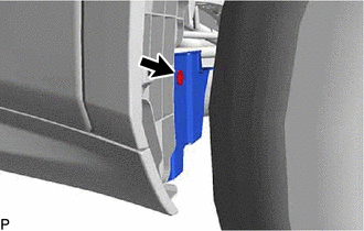
| (c) Remove the clip. |
|
(d) Remove the 2 clips, bolt and No. 1 luggage compartment side cover protector.
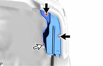
| | Clip |
| | Bolt |
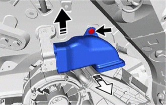
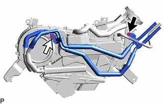
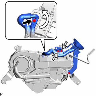
5. DISCONNECT AIR CONDITIONING HOSE AND ACCESSORY
| (a) Remove the bolt and rotate the hook connector as shown in the illustration. |
|
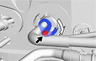
| (b) Disconnect the suction tube. |
|
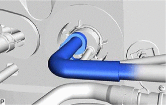
(c) Remove the O-ring from the suction tube.
NOTICE:
Seal the openings of the disconnected parts using vinyl tape to prevent entry of moisture and foreign matter.
| (d) Disconnect the liquid tube. |
|
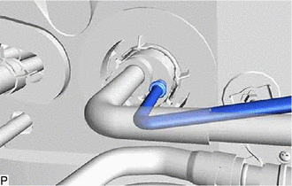
(e) Remove the O-ring from the liquid tube.
NOTICE:
Seal the openings of the disconnected parts using vinyl tape to prevent entry of moisture and foreign matter.
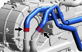
| (f) Using pliers, grip the claws of the clip and slide the clip to disconnect the inlet heater water hose. NOTICE:
|
|
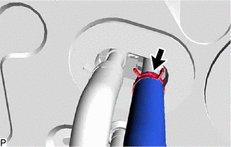
| (g) Using pliers, grip the claws of the clip and slide the clip to disconnect the outlet heater water hose. NOTICE:
|
|
6. REMOVE REAR NO. 2 SEAT ASSEMBLY
Click here
7. REMOVE REAR FLOOR FINISH PLATE
Click here
8. REMOVE REAR DOOR SCUFF PLATE RH
HINT:
Use the same procedure as for the LH side.
Click here
9. REMOVE REAR DOOR INSIDE SCUFF PLATE RH
HINT:
Use the same procedure as for the LH side.
Click here
10. REMOVE REAR SEAT OUTER TRACK BRACKET COVER RH
for 60/40 Split Seat Type:
Click here
for Captain Seat Type:
HINT:
Use the same procedure as for the LH side.
Click here
11. REMOVE FRONT DECK SIDE TRIM COVER RH
HINT:
Use the same procedure as for the LH side.
Click here
12. REMOVE REAR SEAT SIDE GARNISH RH
HINT:
Use the same procedure as for the LH side.
Click here
13. REMOVE NO. 1 LUGGAGE COMPARTMENT TRIM HOOK
Click here
14. REMOVE ROPE HOOK ASSEMBLY
HINT:
Use the same procedure as for the LH side.
Click here
15. REMOVE NO. 1 LUGGAGE COMPARTMENT LIGHT ASSEMBLY
Click here
16. REMOVE DECK TRIM SIDE PANEL ASSEMBLY RH
Click here
17. DISCONNECT REAR NO. 2 SEAT OUTER BELT ASSEMBLY RH
HINT:
Use the same procedure as for the LH side.
Click here
18. REMOVE ROOF SIDE INNER GARNISH ASSEMBLY RH
HINT:
Use the same procedure as for the LH side.
Click here
19. REMOVE REAR NO. 4 SIDE AIR DUCT
(a) Remove the clip.
.png) | Remove in this Direction (1) |
.png) | Remove in this Direction (2) |
(b) Remove the rear No. 4 side air duct as shown in the illustration.
20. REMOVE COOLER PLATE
| (a) Disengage the 2 claws to remove the cooler plate. |
|
21. REMOVE REAR NO. 3 SIDE AIR DUCT
(a) Remove the clip.
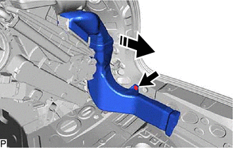
| | Remove in this Direction |
(b) Remove the rear No. 3 side air duct as shown in the illustration.
22. REMOVE REAR NO. 2 SIDE AIR DUCT
(a) Disengage the clamp.
| | Remove in this Direction |
(b) Remove the clip.
(c) Remove the rear No. 2 side air duct as shown in the illustration.
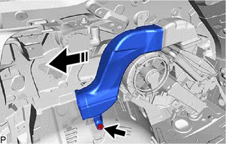
23. REMOVE REAR NO. 1 SIDE AIR DUCT
(a) Remove the clip.
| | Remove in this Direction |
(b) Remove the rear No. 1 side air duct as shown in the illustration.
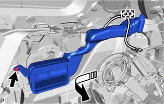
24. REMOVE REAR NO. 7 AIR DUCT
(a) Remove the clip.
| | Remove in this Direction |
(b) Remove the rear No. 7 air duct as shown in the illustration.
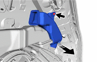
25. REMOVE REAR NO. 6 AIR DUCT
(a) Remove the clip.
| | Remove in this Direction |
(b) Remove the rear No. 6 air duct as shown in the illustration.
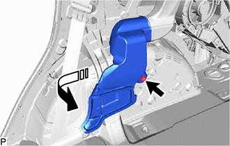
26. REMOVE REAR NO. 5 AIR DUCT
(a) Remove the clip.
| | Remove in this Direction (1) |
| | Remove in this Direction (2) |
(b) Remove the rear No. 5 air duct as shown in the illustration.
27. REMOVE REAR AIR CONDITIONING UNIT ASSEMBLY
| (a) Disconnect each connector. |
|
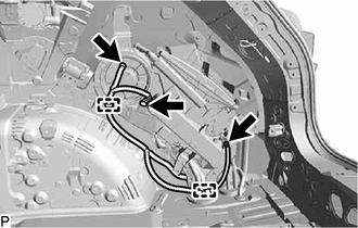
(b) Disengage each clamp.
(c) Disconnect the drain cooler hose.
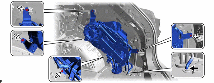
(d) Remove the 4 bolts.
(e) Disengage the guide and remove the rear air conditioning unit assembly.
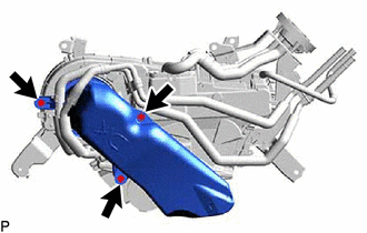
28. REMOVE REAR AIR DUCT
| (a) Remove the 3 screws and rear air duct. |
|
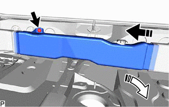
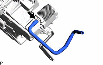
29. REMOVE WATER PIPE AND HOSE SUB-ASSEMBLY A
(a) Remove the bolt and screw.
| | Bolt |
| | Screw |
| (b) Slide the 2 clips and disconnect the water pipe and hose sub-assembly A. NOTICE:
|
|
30. REMOVE NO. 1 COOLING UNIT PACKING
| (a) Remove the No. 1 cooling unit packing. |
|
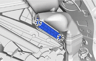
31. REMOVE AIR CONDITIONING TUBE AND ACCESSORY ASSEMBLY
(a) Remove the bolt and rotate the hook connector as shown in the illustration.
| | Bolt |
.png) | Screw |
(b) Remove the 3 screws and air conditioning tube and accessory assembly.
(c) Remove the 2 O-rings from the rear cooling unit expansion valve.
NOTICE:
Seal the openings of the disconnected parts using vinyl tape to prevent entry of moisture and foreign matter.
32. REMOVE DRAIN COOLER HOSE
| (a) Remove the drain cooler hose from the rear cooling unit assembly. |
|
 Reassembly
REASSEMBLY PROCEDURE 1. INSTALL NO. 2 AIR CONDITIONING HARNESS ASSEMBLY (a) Engage the 2 claws to install the No. 2 air conditioning harness assembly. 2. INSTALL REAR EVAPORATOR SUB-ASS ...
 Installation
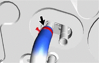
INSTALLATION PROCEDURE 1. INSTALL DRAIN COOLER HOSE (a) Align the hose notch with the rib as shown in the illustration and install the drain cooler hose to the rear cooling unit assembly. ...
Other materials:
Lexus RX (RX 350L, RX450h) 2016-2026 Repair Manual > Washer Level Warning Switch: Components
COMPONENTS ILLUSTRATION *A for TMMC Made - - *1 FRONT FENDER SPLASH SHIELD SUB-ASSEMBLY RH *2 FRONT WHEEL OPENING EXTENSION PAD RH *3 LEVEL WARNING SWITCH ASSEMBLY - - ...
Lexus RX (RX 350L, RX450h) 2016-2026 Repair Manual > Safety Connect System: Problem Symptoms Table
PROBLEM SYMPTOMS TABLE HINT:
Use the table below to help determine the cause of problem symptoms. If multiple suspected areas are listed, the potential causes of the symptoms are listed in order of probability in the "Suspected Area" column of the table. Check each symptom by checking the suspect ...
Lexus RX (RX 350L, RX450h) 2016-{YEAR} Owners Manual
- For your information
- Pictorial index
- For safety and security
- Instrument cluster
- Operation of each component
- Driving
- Lexus Display Audio system
- Interior features
- Maintenance and care
- When trouble arises
- Vehicle specifications
- For owners
Lexus RX (RX 350L, RX450h) 2016-{YEAR} Repair Manual

0.0094