Lexus RX (RX 350L, RX450h) 2016-2026 Repair Manual: Reassembly
REASSEMBLY
PROCEDURE
1. INSTALL NO. 2 AIR CONDITIONING HARNESS ASSEMBLY
| (a) Engage the 2 claws to install the No. 2 air conditioning harness assembly. |
|
.png)
2. INSTALL REAR EVAPORATOR SUB-ASSEMBLY
(a) Install the rear evaporator sub-assembly as shown in the illustration.
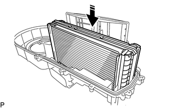
.png) | Install in this Direction |
NOTICE:
When the rear evaporator sub-assembly is removed, make sure to install a new one. The rear evaporator sub-assembly cannot be reused.
| (b) Install the rear cooling unit cover LH to the rear cooling unit cover RH with the 12 screws. |
|
.png)
(c) Engage each clamp.
.png)
3. INSTALL HEATER RADIATOR UNIT SUB-ASSEMBLY
(a) Install the heater radiator unit sub-assembly.
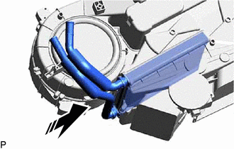
| | Install in this Direction |
4. INSTALL COOLER UNIT CLAMP
| (a) Install the cooler unit clamp with the 2 screws. |
|
.png)
5. INSTALL NO. 3 COOLING UNIT BRACKET
| (a) Install the No. 3 cooling unit bracket with the 2 screws. |
|
.png)
6. INSTALL NO. 2 COOLING UNIT BRACKET
| (a) Install the No. 2 cooling unit bracket with the 2 screws. |
|
.png)
7. INSTALL NO. 1 COOLING UNIT BRACKET
| (a) Install the No. 1 cooling unit bracket with the 3 screws. |
|
.png)
8. INSTALL REAR COOLING UNIT EXPANSION VALVE
(a) Remove the vinyl tape from the rear cooling unit expansion valve and rear evaporator sub-assembly.
(b) Sufficiently apply compressor oil to 2 new O-rings and the fitting surfaces of the rear cooling unit expansion valve.
Compressor Oil:
ND-OIL 12 or equivalent
(c) Install the 2 O-rings to the air conditioner tube and accessory assembly.
NOTICE:
Keep the O-rings and O-ring fitting surface free of foreign matter.
| (d) Using a 4 mm hexagon socket wrench, install the rear cooling unit expansion valve with the 2 hexagon bolts. Torque: 3.5 N·m {36 kgf·cm, 31 in·lbf} |
|
.png)
| (e) Install the grommet. |
|
.png)
| (f) Engage the 3 claws to install the plate. |
|
.png)
9. INSTALL REAR NO. 1 COOLING UNIT DAMPER SERVO SUB-ASSEMBLY
| (a) Using the reference points, install the rear No. 1 cooling damper servo sub-assembly with the 2 screws. |
|
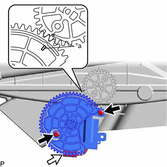
(b) Connect the connector.
10. INSTALL REAR NO. 2 COOLING UNIT DAMPER SERVO SUB-ASSEMBLY
| (a) Using the reference points, install the rear No. 2 cooling damper servo sub-assembly with the 2 screws. |
|
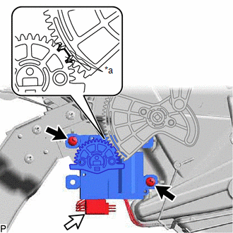
(b) Connect the connector.
11. INSTALL BLOWER MOTOR CONTROL
| (a) Install the blower motor control with the 2 screws. |
|
.png)
12. INSTALL REAR BLOWER MOTOR WITH FAN SUB-ASSEMBLY
| (a) Install the rear blower motor with fan sub-assembly with the 3 screws. NOTICE: Replace the rear blower motor with fan sub-assembly if it has been dropped or subjected to a severe impact. |
|
.png)
 Disassembly
DISASSEMBLY PROCEDURE 1. REMOVE REAR BLOWER MOTOR WITH FAN SUB-ASSEMBLY (a) Remove the 3 screws and rear blower motor with fan sub-assembly. 2. REMOVE BLOWER MOTOR CONTROL (a) Remove ...
 Removal
REMOVAL CAUTION / NOTICE / HINT The necessary procedures (adjustment, calibration, initialization, or registration) that must be performed after parts are removed and installed, or replaced during rea ...
Other materials:
Lexus RX (RX 350L, RX450h) 2016-2026 Repair Manual > Park / Neutral Position Switch: Removal
REMOVAL CAUTION / NOTICE / HINT The necessary procedures (adjustment, calibration, initialization or registration) that must be performed after parts are removed and installed, or replaced during park/neutral position switch assembly removal/installation are shown below. Necessary Procedures After P ...
Lexus RX (RX 350L, RX450h) 2016-2026 Repair Manual > Rear Combination Light Assembly (w/o Rear No. 2 Seat): Disassembly
DISASSEMBLY CAUTION / NOTICE / HINT HINT:
Use the same procedure for the RH side and LH side.
The following procedure is for the LH side.
PROCEDURE 1. REMOVE REAR COMBINATION LIGHT CAP (for LED Type Turn Signal Light) (a) for TMMC Made: (1) Remove the rear combination light cap. HINT: Use ...
Lexus RX (RX 350L, RX450h) 2016-{YEAR} Owners Manual
- For your information
- Pictorial index
- For safety and security
- Instrument cluster
- Operation of each component
- Driving
- Lexus Display Audio system
- Interior features
- Maintenance and care
- When trouble arises
- Vehicle specifications
- For owners
Lexus RX (RX 350L, RX450h) 2016-{YEAR} Repair Manual

0.0099