Lexus RX (RX 350L, RX450h) 2016-2026 Repair Manual: Disassembly
DISASSEMBLY
PROCEDURE
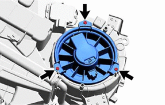
1. REMOVE REAR BLOWER MOTOR WITH FAN SUB-ASSEMBLY
| (a) Remove the 3 screws and rear blower motor with fan sub-assembly. |
|
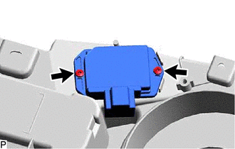
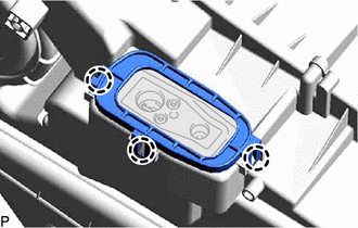
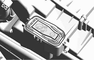
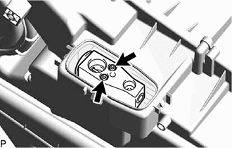
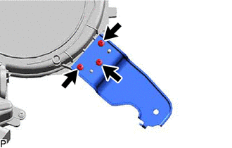
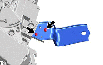
2. REMOVE BLOWER MOTOR CONTROL
| (a) Remove the 2 screws and blower motor control. |
|
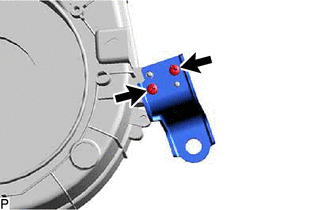
3. REMOVE REAR NO. 2 COOLING UNIT DAMPER SERVO SUB-ASSEMBLY
| (a) Disconnect the connector. |
|
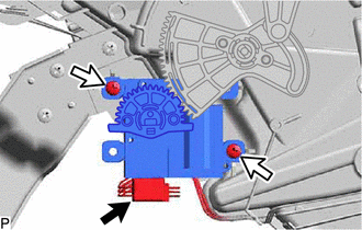
(b) Remove the 2 screws and rear No. 2 cooler unit damper servo sub-assembly.
4. REMOVE REAR NO. 1 COOLING UNIT DAMPER SERVO SUB-ASSEMBLY
| (a) Disconnect the connector. |
|
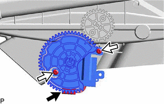
(b) Remove the 2 screws and rear No. 1 cooler unit damper servo sub-assembly.
5. REMOVE REAR COOLING UNIT EXPANSION VALVE
| (a) Disengage the 3 claws to remove the plate. |
|
| (b) Remove the grommet. |
|
| (c) Using a 4 mm hexagon socket wrench, remove the 2 hexagon bolts and rear cooling unit expansion valve. |
|
(d) Remove the 2 O-rings from the rear evaporator sub-assembly.
NOTICE:
Seal the openings of the disconnected parts using vinyl tape to prevent entry of moisture and foreign matter.
6. REMOVE NO. 1 COOLING UNIT BRACKET
| (a) Remove the 3 screws and No. 1 cooling unit bracket. |
|
7. REMOVE NO. 2 COOLING UNIT BRACKET
| (a) Remove the 2 screws and No. 2 cooling unit bracket. |
|
8. REMOVE NO. 3 COOLING UNIT BRACKET
| (a) Remove the 2 screws and No. 3 cooling unit bracket. |
|
9. REMOVE COOLER UNIT CLAMP
| (a) Remove the 2 screws and cooler unit clamp. |
|
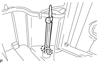
10. REMOVE HEATER RADIATOR UNIT SUB-ASSEMBLY
(a) Remove the heater radiator unit sub-assembly as shown in the illustration.
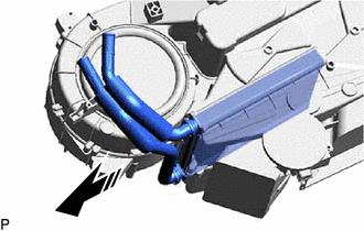
.png) | Remove in this Direction |
NOTICE:
Prepare a drain pan or cloth in case the coolant leaks.
11. REMOVE REAR EVAPORATOR SUB-ASSEMBLY
(a) Disengage each clamp.
| (b) Remove the 12 screws and rear cooling unit cover LH from the rear cooling unit cover RH. |
|
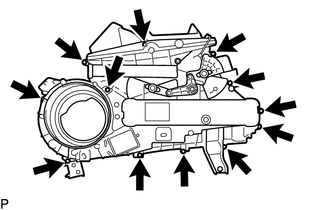
(c) Remove the rear evaporator sub-assembly as shown in the illustration.
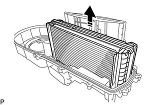
| | Remove in this Direction |
NOTICE:
When the rear evaporator sub-assembly is removed, make sure to install a new one. The rear evaporator sub-assembly cannot be reused.
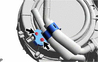
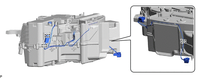
12. REMOVE NO. 2 AIR CONDITIONING HARNESS ASSEMBLY
| (a) Disengage the 2 claws to remove the No. 2 air conditioning harness assembly. |
|
 Components
COMPONENTS ILLUSTRATION *1 AIR CONDITIONING HOSE AND ACCESSORY *2 NO. 1 LUGGAGE COMPARTMENT SIDE COVER PROTECTOR *3 SUCTION TUBE *4 LIQUID TUBE *5 INLET HEATER WATER HOSE * ...
 Reassembly
REASSEMBLY PROCEDURE 1. INSTALL NO. 2 AIR CONDITIONING HARNESS ASSEMBLY (a) Engage the 2 claws to install the No. 2 air conditioning harness assembly. 2. INSTALL REAR EVAPORATOR SUB-ASS ...
Other materials:
Lexus RX (RX 350L, RX450h) 2016-2026 Repair Manual > Power Steering System: EPS Warning Light Circuit
DESCRIPTION If the power steering ECU assembly detects a malfunction, the power steering ECU assembly stores a DTC and illuminates the EPS warning light. WIRING DIAGRAM CAUTION / NOTICE / HINT NOTICE:
If the power steering ECU assembly has been replaced, perform assist map writing and torque sen ...
Lexus RX (RX 350L, RX450h) 2016-2026 Repair Manual > Dynamic Radar Cruise Control System: Problem Symptoms Table
PROBLEM SYMPTOMS TABLE NOTICE:
Before replacing the ECM, refer to Registration.
Click here
When replacing the millimeter wave radar sensor assembly, always replace it with a new one. If a millimeter wave radar sensor assembly which was installed to another vehicle is used, the information st ...
Lexus RX (RX 350L, RX450h) 2016-{YEAR} Owners Manual
- For your information
- Pictorial index
- For safety and security
- Instrument cluster
- Operation of each component
- Driving
- Lexus Display Audio system
- Interior features
- Maintenance and care
- When trouble arises
- Vehicle specifications
- For owners
Lexus RX (RX 350L, RX450h) 2016-{YEAR} Repair Manual

0.0089