Lexus RX (RX 350L, RX450h) 2016-2026 Repair Manual: Disassembly
DISASSEMBLY
PROCEDURE
1. REMOVE REAR CENTER ULTRASONIC SENSOR (w/ Intuitive Parking Assist System)
Click here .gif)
2. REMOVE REAR CORNER ULTRASONIC SENSOR (w/ Intuitive Parking Assist System)
Click here
3. REMOVE REAR CENTER ULTRASONIC SENSOR RETAINER (w/ Intuitive Parking Assist System)
Click here
4. REMOVE REAR CORNER ULTRASONIC SENSOR RETAINER (w/ Intuitive Parking Assist System)
Click here
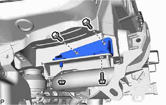
5. REMOVE KICK DOOR CONTROL SENSOR WITH BRACKET (for TMC Made with Kick Sensor)
except F-Sport:
Click here
for F-Sport:
Click here
6. REMOVE NO. 3 LUGGAGE ROOM WIRE (w/o Intuitive Parking Assist System)
(a) for TMMC Made with Kick Sensor:
(1) Disconnect the connector.
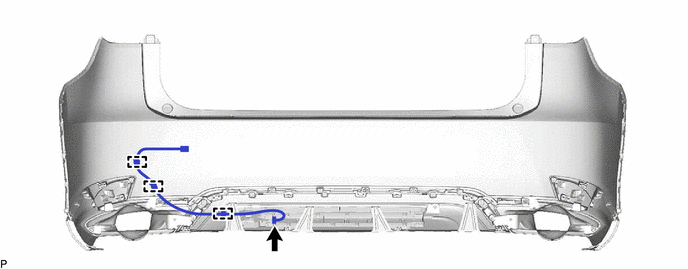
(2) Disengage the 3 clamps to remove the No. 3 luggage room wire.
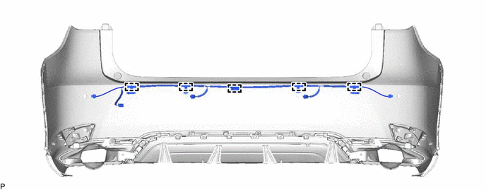
7. REMOVE NO. 3 LUGGAGE ROOM WIRE (w/ Intuitive Parking Assist System)
(a) for TMC Made without Kick Sensor:
(1) Disengage the 5 clamps to remove the No. 3 luggage room wire.
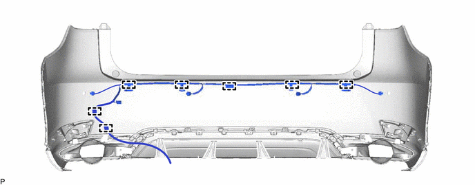
(b) for TMC Made with Kick Sensor:
(1) Disengage the 7 clamps to remove the No. 3 luggage room wire.
(c) for TMMC Made with Kick Sensor:
(1) Disconnect the connector.
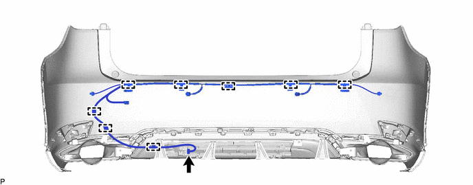
(2) Disengage the 8 clamps to remove the No. 3 luggage room wire.
8. REMOVE ULTRASONIC SENSOR CLIP (w/o Intuitive Parking Assist System)
HINT:
When removing the ultrasonic sensor clip, heat the rear bumper assembly and ultrasonic sensor clip using a heat light.
Heating Temperature:
| Item | Temperature |
|---|---|
| Ultrasonic Sensor Clip and Rear Bumper Assembly | 20 to 30°C (68 to 86°F) |
CAUTION:
- Do not touch the heat light and heated parts, touching the heat light may result in burns.
- Touching heated parts for a long time may result in burns.
.png)
| *a | Heated Part |
| *b | Heat Light |
NOTICE:
Do not heat the rear bumper assembly or ultrasonic sensor clip excessively.
(a) Using a heat light, heat the rear bumper assembly and ultrasonic sensor clip.
(b) w/ Kick Sensor:
(1) Remove the 2 ultrasonic sensor clips.
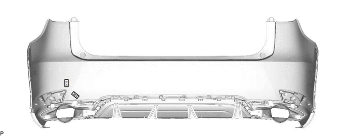
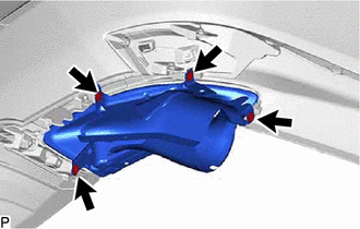
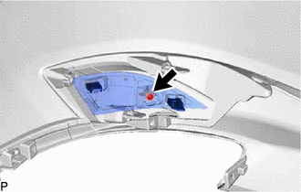
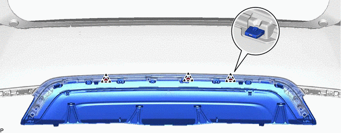
9. REMOVE ULTRASONIC SENSOR CLIP (w/ Intuitive Parking Assist System)
HINT:
When removing the ultrasonic sensor clip, heat the rear bumper assembly and ultrasonic sensor clip using a heat light.
Heating Temperature:
| Item | Temperature |
|---|---|
| Ultrasonic Sensor Clip and Rear Bumper Assembly | 20 to 30°C (68 to 86°F) |
CAUTION:
- Do not touch the heat light and heated parts, touching the heat light may result in burns.
- Touching heated parts for a long time may result in burns.
| *a | Heated Part |
| *b | Heat Light |
NOTICE:
Do not heat the rear bumper assembly or ultrasonic sensor clip excessively.
(a) Using a heat light, heat the rear bumper assembly and ultrasonic sensor clip.
(b) Remove each ultrasonic sensor clip.
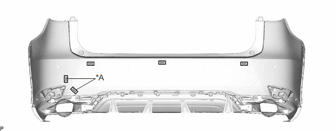
| *A | w/ Kick Sensor | - | - |
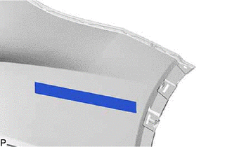
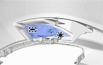
10. REMOVE NO. 1 MOULDING TAPE
| (a) Remove the No. 1 moulding tape. HINT: Use the same procedure for the RH side and LH side. |
|
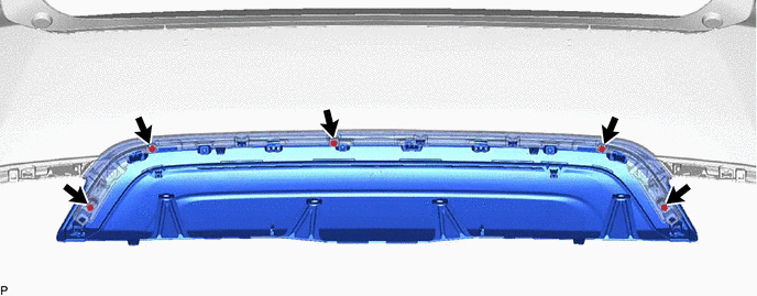
11. REMOVE REAR BUMPER EXTENSION SUB-ASSEMBLY LH
| (a) Remove the 4 screws. |
|
| (b) Remove the 4 grommets to rear bumper extension sub-assembly LH. |
|
12. REMOVE REAR BUMPER EXTENSION SUB-ASSEMBLY RH
HINT:
Use the same procedure as for the LH side.
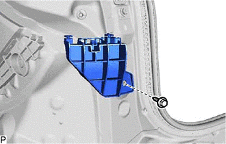
13. REMOVE REFLEX REFLECTOR ASSEMBLY LH
| (a) Remove the screw. |
|
| (b) Disengage the claw and guide to remove the reflex reflector assembly LH. |
|
14. REMOVE REFLEX REFLECTOR ASSEMBLY RH
HINT:
Use the same procedure as for the LH side.
15. REMOVE CENTER REAR BUMPER EXTENSION SUB-ASSEMBLY
(a) for TMMC Made with Kick Sensor:
(1) Remove the kick door control sensor with bracket.
except F-Sport:
Click here
for F-Sport:
Click here
(b) Remove the 5 screws.
(c) Disengage the 3 clips to remove the center rear bumper extension sub-assembly.
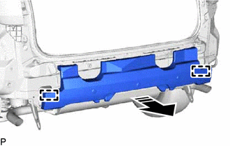
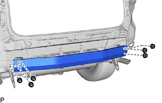
16. REMOVE REAR BUMPER EXTENSION RETAINER LH
(a) Remove the 3 screws and 2 clips.
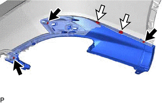
.png) | Screw |
.png) | Clip |
| (b) Disengage the 2 claws, clip and guide to remove the rear bumper extension retainer LH. |
|
17. REMOVE REAR BUMPER EXTENSION RETAINER RH
HINT:
Use the same procedure as for the LH side.
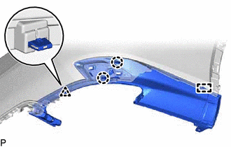
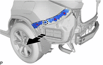
18. REMOVE REAR BUMPER SIDE RETAINER LH
(a) Disengage the 3 clips as shown in the illustration.
.png) | Remove in this Direction |
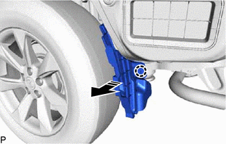
(b) Disengage the claw as shown in the illustration to remove the rear bumper side retainer LH.
| | Remove in this Direction |
19. REMOVE REAR BUMPER SIDE RETAINER RH
HINT:
Use the same procedure as for the LH side.
20. DISCONNECT REAR WHEEL HOUSE LINER LH
| (a) Remove the 2 screws and grommet and disconnect the rear wheel house liner LH. |
|
21. DISCONNECT REAR WHEEL HOUSE LINER RH
HINT:
Use the same procedure as for the LH side.
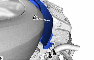
22. REMOVE LOWER REAR BUMPER RETAINER LH
| (a) Remove the 2 screws. |
|
(b) Disengage the claw as shown in the illustration to remove the lower rear bumper retainer LH.
| | Remove in this Direction |
23. REMOVE LOWER REAR BUMPER RETAINER RH
HINT:
Use the same procedure as for the LH side.
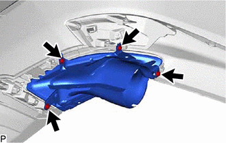
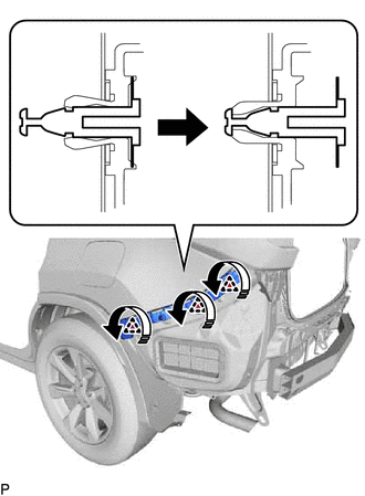
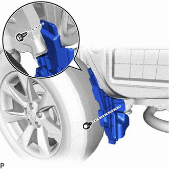
24. REMOVE REAR BUMPER ENERGY ABSORBER
(a) Disengage the 2 guides as shown in the illustration to remove the rear bumper energy absorber.
| | Remove in this Direction |
25. REMOVE NO. 1 REAR BUMPER REINFORCEMENT (w/o Towing Hitch)
| (a) Remove the 6 nuts and No. 1 rear bumper reinforcement. |
|
26. REMOVE REAR COMBINATION LIGHT ASSEMBLY LH
Click here
27. REMOVE REAR COMBINATION LIGHT ASSEMBLY RH
HINT:
Use the same procedure as for the LH side.
28. REMOVE UPPER REAR BUMPER RETAINER LH
| (a) Remove the screw and upper rear bumper retainer LH. |
|
29. REMOVE UPPER REAR BUMPER RETAINER RH
HINT:
Use the same procedure as for the LH side.
30. REMOVE TOWING SOCKET (w/ Towing Hitch)
Click here
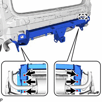
31. REMOVE RECEIVER HITCH BRACKET LH (w/ Towing Hitch)
| (a) Remove the nut. |
|
(b) Remove the 3 bolts and receiver hitch bracket LH.
32. REMOVE RECEIVER HITCH BRACKET RH (w/ Towing Hitch)
| (a) Remove the 4 bolts and receiver hitch bracket RH. |
|
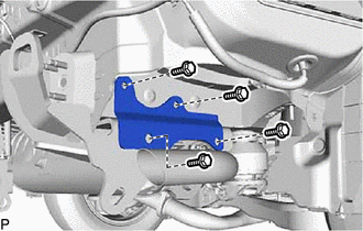
33. REMOVE RECEIVER HITCH BRACKET SUB-ASSEMBLY (w/ Towing Hitch)
(a) w/ Intuitive Parking Assist System or Kick Sensor:
| (1) Disengage the clamp. |
|
(b) Remove the 6 bolts and receiver hitch bracket sub-assembly.
NOTICE:
Because the receiver hitch bracket sub-assembly is very heavy, it may cause injury or fall resulting in damage to the vehicle body when it is being handled. During removal or installation, make sure that there are enough people available to hold the hitch bracket securely.
 Removal
REMOVAL CAUTION / NOTICE / HINT The necessary procedures (adjustment, calibration, initialization, or registration) that must be performed after parts are removed and installed, or replaced during rea ...
 Installation
INSTALLATION PROCEDURE 1. INSTALL REAR BUMPER ASSEMBLY (a) w/ Intuitive Parking Assist System or Kick Sensor: (1) Connect the connector. (b) Engage the 2 claws as shown in the illustration. Ins ...
Other materials:
Lexus RX (RX 350L, RX450h) 2016-2026 Repair Manual > Rear Power Seat Control System(for Third Row): Terminals Of Ecu
TERMINALS OF ECU CHECK FOLD SEAT CONTROL ECU (RH SEAT) (a) Disconnect the x15 and x16 fold seat control ECU (RH seat) connectors. (b) Measure the resistance and voltage according to the value(s) in the table below. Terminal No. (Symbol) Wiring Color Terminal Description Condition Specifi ...
Lexus RX (RX 350L, RX450h) 2016-2026 Repair Manual > Rear No. 1 Seat Assembly (for Captain Seat Type): Disassembly
DISASSEMBLY CAUTION / NOTICE / HINT CAUTION: Wear protective gloves. Sharp areas on the seat frame may injure your hands. HINT:
Use the same procedure for the RH side and LH side.
The following procedure is for the LH side.
PROCEDURE 1. REMOVE SEAT ADJUSTER COVER CAP (a) Remove the 2 seat ...
Lexus RX (RX 350L, RX450h) 2016-{YEAR} Owners Manual
- For your information
- Pictorial index
- For safety and security
- Instrument cluster
- Operation of each component
- Driving
- Lexus Display Audio system
- Interior features
- Maintenance and care
- When trouble arises
- Vehicle specifications
- For owners
Lexus RX (RX 350L, RX450h) 2016-{YEAR} Repair Manual

0.0088