Lexus RX (RX 350L, RX450h) 2016-2026 Repair Manual: Removal
REMOVAL
CAUTION / NOTICE / HINT
The necessary procedures (adjustment, calibration, initialization, or registration) that must be performed after parts are removed and installed, or replaced during rear bumper assembly removal/installation are shown below.
Necessary Procedures After Parts Removed/Installed/Replaced| Replaced Part or Performed Procedures | Necessary Procedures | Effect/Inoperative Function When Necessary Procedures are not Performed | Link |
|---|---|---|---|
|
*1: When performing learning using the Techstream.
Click here | |||
| w/ Kick Sensor
| Memorize steering angle neutral point | Lane Control System | |
| Pre-collision System | |||
| Intelligent Clearance Sonar System*1 | |||
| Parking Assist Monitor System | | ||
| Panoramic View Monitor System | | ||
| Lighting System (w/ Automatic Headlight Beam Level Control System) | | ||
| Initialize back door lock | Power Door Lock Control System | | |
| Reset back door close position | Power Back Door System (w/ Outside Door Control Switch) | | |
| w/ Intelligent Clearance Sonar System
|
|
| |
PROCEDURE
1. PRECAUTION (w/ Kick Sensor)
NOTICE:
After turning the engine switch off, waiting time may be required before disconnecting the cable from the negative (-) battery terminal. Therefore, make sure to read the disconnecting the cable from the negative (-) battery terminal notices before proceeding with work.
Click here .gif)
2. DISCONNECT CABLE FROM NEGATIVE BATTERY TERMINAL (w/ Kick Sensor)
NOTICE:
When disconnecting the cable, some systems need to be initialized after the cable is reconnected.
Click here
3. REMOVE REAR LIGHT COVER LH
for Bulb Type Turn Signal Light:
Click here
for LED Type Turn Signal Light:
Click here
4. REMOVE REAR LIGHT COVER RH
HINT:
Use the same procedure as for the LH side.
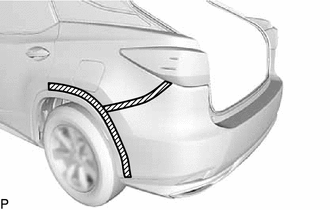
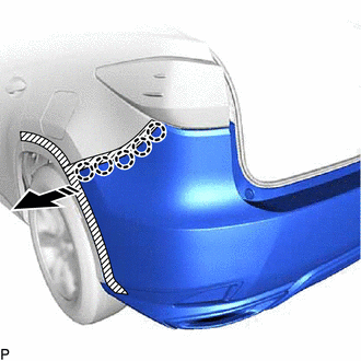
5. DISCONNECT QUARTER OUTSIDE MOULDING SUB-ASSEMBLY LH
(a) Apply protective tape around the quarter outside moulding sub-assembly LH and rear bumper assembly as shown in the illustration.
.png) | Protective Tape |
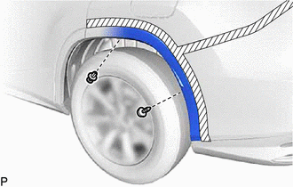
| (b) Using a 4 mm hexagon socket wrench, remove the screw. |
|
(c) Remove the clip.
(d) Pull back the edge of the rear wheel house liner LH and disengage the 4 claws by pushing the area indicated by the arrow in the illustration with a finger.
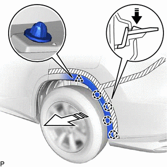
.png) | Remove in this Direction (1) |
.png) | Remove in this Direction (2) |
NOTICE:
- Do not apply excessive force when pulling back the rear wheel house liner LH.
- To avoid damaging the claws, do not forcibly pull the quarter outside moulding sub-assembly LH.
(e) Disengage the clip to disconnect the quarter outside moulding sub-assembly LH from the rear bumper assembly.
6. DISCONNECT QUARTER OUTSIDE MOULDING SUB-ASSEMBLY RH
HINT:
Use the same procedure as for the LH side.
7. REMOVE REAR BUMPER ASSEMBLY
| (a) Remove the 4 screws. |
|
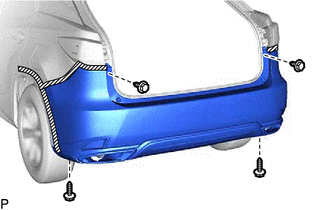
| (b) Remove the 6 clips. |
|
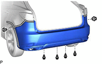
(c) Disengage the 5 claws as shown in the illustration.
| | Remove in this Direction |
HINT:
Use the same procedure for the RH side and LH side.
(d) Disengage the 2 claws as shown in the illustration to remove the rear bumper assembly.
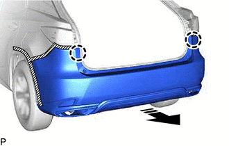
| | Remove in this Direction |
(e) w/ Intuitive Parking Assist System or Kick Sensor:
(1) Disconnect the connector.
 Components
COMPONENTS ILLUSTRATION *1 QUARTER OUTSIDE MOULDING SUB-ASSEMBLY LH *2 QUARTER OUTSIDE MOULDING SUB-ASSEMBLY RH *3 REAR BUMPER ASSEMBLY *4 REAR LIGHT COVER LH *5 REAR LIGHT C ...
 Disassembly
DISASSEMBLY PROCEDURE 1. REMOVE REAR CENTER ULTRASONIC SENSOR (w/ Intuitive Parking Assist System) Click here 2. REMOVE REAR CORNER ULTRASONIC SENSOR (w/ Intuitive Parking Assist System) Click here ...
Other materials:
Lexus RX (RX 350L, RX450h) 2016-2026 Repair Manual > Power Mirror Control System (w/ Memory): Front Passenger Side Power Mirror cannot be Adjusted with Power Mirror Switch
DESCRIPTION The multiplex network master switch assembly sends the mirror adjust switch signals to the main body ECU (multiplex network body ECU) via LIN communication. The main body ECU (multiplex network body ECU) then sends the received mirror adjust switch signals to the outer mirror control ECU ...
Lexus RX (RX 350L, RX450h) 2016-2026 Repair Manual > Dynamic Radar Cruise Control System: Invalid Data Received from ECM/PCM "A" Invalid Serial Data Received (U040181)
DESCRIPTION If the ECM cannot recognize the forward recognition camera. DTC U040181 is stored. DTC No. Detection Item DTC Detection Condition Trouble Area MIL DTC Output from U040181 Invalid Data Received from ECM/PCM "A" Invalid Serial Data Received Approximately 17 seconds or ...
Lexus RX (RX 350L, RX450h) 2016-{YEAR} Owners Manual
- For your information
- Pictorial index
- For safety and security
- Instrument cluster
- Operation of each component
- Driving
- Lexus Display Audio system
- Interior features
- Maintenance and care
- When trouble arises
- Vehicle specifications
- For owners
Lexus RX (RX 350L, RX450h) 2016-{YEAR} Repair Manual

0.0102