Lexus RX (RX 350L, RX450h) 2016-2026 Repair Manual: Installation
INSTALLATION
PROCEDURE
1. INSTALL REAR BUMPER ASSEMBLY
(a) w/ Intuitive Parking Assist System or Kick Sensor:
(1) Connect the connector.
(b) Engage the 2 claws as shown in the illustration.
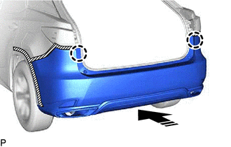
.png) | Install in this Direction |
(c) Engage the 5 claws as shown in the illustration.
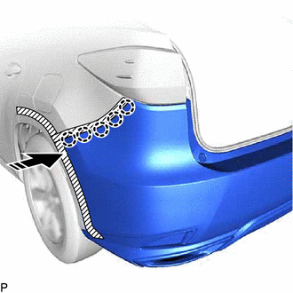
| | Install in this Direction |
HINT:
Use the same procedure for the RH side and LH side.
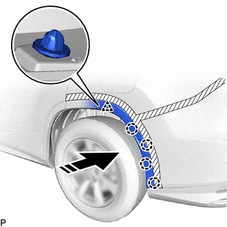
(d) Install the 6 clips.
(e) Install the rear bumper assembly with the 4 screws.
2. CONNECT QUARTER OUTSIDE MOULDING SUB-ASSEMBLY LH
(a) Engage the clip and 4 claws as shown in the illustration.
| | Install in this Direction |
(b) Using a 4 mm hexagon socket wrench, install the screw.
(c) Install the quarter outside moulding sub-assembly LH with the clip.
3. CONNECT QUARTER OUTSIDE MOULDING SUB-ASSEMBLY RH
HINT:
Use the same procedure as for the LH side.
4. INSTALL REAR LIGHT COVER LH
for Bulb Type Turn Signal Light:
Click here .gif)
for LED Type Turn Signal Light:
Click here
5. INSTALL REAR LIGHT COVER RH
HINT:
Use the same procedure as for the LH side.
6. CONNECT CABLE TO NEGATIVE BATTERY TERMINAL (w/ Kick Sensor)
NOTICE:
When disconnecting the cable, some systems need to be initialized after the cable is reconnected.
Click here
7. PERFORM CALIBRATION (w/ Intelligent Clearance Sonar System)
Click here
8. INSPECT KICK DOOR CONTROL SENSOR (w/ Kick Sensor)
Click here
 Disassembly
DISASSEMBLY PROCEDURE 1. REMOVE REAR CENTER ULTRASONIC SENSOR (w/ Intuitive Parking Assist System) Click here 2. REMOVE REAR CORNER ULTRASONIC SENSOR (w/ Intuitive Parking Assist System) Click here ...
 Reassembly
REASSEMBLY PROCEDURE 1. INSTALL RECEIVER HITCH BRACKET SUB-ASSEMBLY (w/ Towing Hitch) (a) Install the receiver hitch bracket sub-assembly with the 6 bolts. Torque: 80 N·m {816 kgf·cm, 59 ft·lbf ...
Other materials:
Lexus RX (RX 350L, RX450h) 2016-2026 Repair Manual > Oil And Oil Filter: Components
COMPONENTS ILLUSTRATION *1 OIL FILTER CAP ASSEMBLY *2 OIL FILTER ELEMENT *3 OIL FILLER CAP SUB-ASSEMBLY *4 O-RING *5 GASKET *6 OIL PAN DRAIN PLUG *7 OIL FILTER DRAIN PLUG - - Tightening torque for "Major areas involving basic vehicle performance such as ...
Lexus RX (RX 350L, RX450h) 2016-2026 Repair Manual > Automatic Transaxle Unit: Components
COMPONENTS ILLUSTRATION *1 TRANSMISSION CONTROL SHAFT LEVER *2 PARK/NEUTRAL POSITION SWITCH ASSEMBLY *3 LOCK NUT *4 LOCK PLATE *5 TRANSMISSION CASE PLUG ASSEMBLY *6 NO. 1 BREATHER PLUG (ATM) *7 TRANSMISSION BREATHER CLAMP *8 BREATHER PLUG HOSE *9 BREATHE ...
Lexus RX (RX 350L, RX450h) 2016-{YEAR} Owners Manual
- For your information
- Pictorial index
- For safety and security
- Instrument cluster
- Operation of each component
- Driving
- Lexus Display Audio system
- Interior features
- Maintenance and care
- When trouble arises
- Vehicle specifications
- For owners
Lexus RX (RX 350L, RX450h) 2016-{YEAR} Repair Manual

0.0105