Lexus RX (RX 350L, RX450h) 2016-2026 Repair Manual: GVIF Disconnected (from Extension Module to H/U) (B153A)
DESCRIPTION
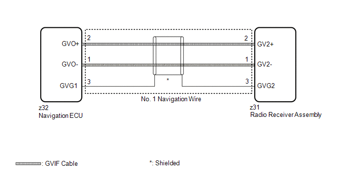
The radio receiver assembly and navigation ECU are connected via video signal (digital) lines.
This DTC is stored when a video signal (digital) line is disconnected.
| DTC No. | Detection Item | DTC Detection Condition | Trouble Area |
|---|---|---|---|
| B153A | GVIF Disconnected (from Extension Module to H/U) | GVIF disconnected (from navigation ECU to radio receiver assembly) |
|
WIRING DIAGRAM
CAUTION / NOTICE / HINT
NOTICE:
Depending on the parts that are replaced during vehicle inspection or maintenance, performing initialization, registration or calibration may be needed. Refer to Precaution for Audio and Visual System.
Click here .gif)
PROCEDURE
| 1. | CHECK DTC |
(a) Clear the DTCs.
Body Electrical > Navigation System > Clear DTCs(b) Turn the engine switch off.
(c) Turn the engine switch on (IG).
(d) Press the "MAP" switch and check for DTCs.
Body Electrical > Navigation System > Trouble CodesOK:
No DTCs are output.
| OK |  | USE SIMULATION METHOD TO CHECK |
|

| 2. | CHECK NO. 1 NAVIGATION WIRE (RADIO RECEIVER ASSEMBLY - NAVIGATION ECU) |
| (a) Disconnect the z31 radio receiver assembly connector. |
|
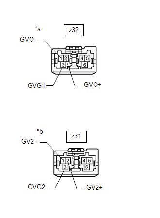
(b) Disconnect the z32 navigation ECU connector.
(c) Measure the resistance according to the value(s) in the table below.
Standard Resistance:
| Tester Connection | Condition | Specified Condition |
|---|---|---|
| z31-1 (GV2-) - z32-1 (GVO-) | Always | Below 1 Ω |
| z31-2 (GV2+) - z32-2 (GVO+) | Always | Below 1 Ω |
| z31-3 (GVG2) - z32-3 (GVG1) | Always | Below 1 Ω |
| NG | | REPLACE NO. 1 NAVIGATION WIRE |
|
| 3. | REPLACE NAVIGATION ECU |
(a) Replace the Navigation ECU with a new or known good one.
Click here
|
| 4. | CHECK DTC |
(a) Clear the DTCs.
Body Electrical > Navigation System > Clear DTCs(b) Turn the engine switch off.
(c) Turn the engine switch on (IG).
(d) Press the "MAP" switch and check for DTCs.
Body Electrical > Navigation System > Trouble CodesOK:
No DTCs are output.
| OK | | END (NAVIGATION ECU IS DEFECTIVE) |
| NG | | REPLACE RADIO RECEIVER ASSEMBLY |
 NTSC Disconnected (from Park Assist/Monitoring ECU) (B1535,C1622)
DESCRIPTION These DTCs are stored if the radio receiver assembly judges that the signals or signal lines between the rear television camera assembly and the multi-display assembly are not normal as a ...
 Extension Module Disconnected 2 (B1543)
DESCRIPTION If the radio receiver assembly cannot detect the navigation ECU for a certain period of time (90 seconds) after the engine switch is turned on (ACC) and the radio receiver assembly confirm ...
Other materials:
Lexus RX (RX 350L, RX450h) 2016-2026 Repair Manual > Sfi System: Actuator Supply Voltage "A" Circuit Short to Ground or Open (P065714)
DESCRIPTION The electronic throttle control system has a dedicated power supply circuit. The voltage (+BM) is monitored and when it is low (less than 4 V), the ECM determines that there is a malfunction in the electronic throttle control system and cuts off the current to the throttle actuator. When ...
Lexus RX (RX 350L, RX450h) 2016-2026 Repair Manual > Dynamic Torque Control Awd System: AWD Control Switch Circuit
DESCRIPTION The 4WD ECU assembly changes the control mode in response to the "Lock Mode" signal from the AWD lock switch (combination switch assembly). WIRING DIAGRAM CAUTION / NOTICE / HINT NOTICE: When the 4WD ECU assembly is replaced with a known good one from another vehicle, it is necessary to ...
Lexus RX (RX 350L, RX450h) 2016-{YEAR} Owners Manual
- For your information
- Pictorial index
- For safety and security
- Instrument cluster
- Operation of each component
- Driving
- Lexus Display Audio system
- Interior features
- Maintenance and care
- When trouble arises
- Vehicle specifications
- For owners
Lexus RX (RX 350L, RX450h) 2016-{YEAR} Repair Manual

0.0099