Lexus RX (RX 350L, RX450h) 2016-2026 Repair Manual: Reassembly
REASSEMBLY
PROCEDURE
1. INSTALL RECEIVER HITCH BRACKET SUB-ASSEMBLY (w/ Towing Hitch)
| (a) Install the receiver hitch bracket sub-assembly with the 6 bolts. Torque: 80 N·m {816 kgf·cm, 59 ft·lbf} NOTICE: Because the receiver hitch bracket sub-assembly is very heavy, it may cause injury or fall resulting in damage to the vehicle body when it is being handled. During removal or installation, make sure that there are enough people available to hold the hitch bracket securely. |
|
.png)
(b) w/ Intuitive Parking Assist System or Kick Sensor:
(1) Engage the clamp.
2. INSTALL RECEIVER HITCH BRACKET LH (w/ Towing Hitch)
| (a) Install the receiver hitch bracket LH with the 3 bolts and nut. Torque: 80 N·m {816 kgf·cm, 59 ft·lbf} |
|
.png)
3. INSTALL RECEIVER HITCH BRACKET RH (w/ Towing Hitch)
| (a) Install the receiver hitch bracket RH with the 4 bolts. Torque: 80 N·m {816 kgf·cm, 59 ft·lbf} |
|
.png)
4. INSTALL TOWING SOCKET (w/ Towing Hitch)
Click here .gif)
5. INSTALL UPPER REAR BUMPER RETAINER LH
(a) Engage the 2 guides and install the upper rear bumper retainer LH as shown in the illustration to the rear combination light assembly LH.
.png)
.png) | Install in this Direction |
(b) Engage the grommet.
(c) Engage the guide and pin as shown in the illustration.
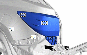
| *a | Guide |
| *b | Pin |
| | Install in this Direction |
(d) Install the upper rear bumper retainer LH with rear combination light assembly LH with the screw.
6. INSTALL UPPER REAR BUMPER RETAINER RH
HINT:
Use the same procedure as for the LH side.
7. INSTALL REAR COMBINATION LIGHT ASSEMBLY LH
Click here
8. INSTALL REAR COMBINATION LIGHT ASSEMBLY RH
HINT:
Use the same procedure as for the LH side.
9. INSTALL NO. 1 REAR BUMPER REINFORCEMENT (w/o Towing Hitch)
| (a) Install the No. 1 rear bumper reinforcement with the 6 nuts. Torque: 35 N·m {357 kgf·cm, 26 ft·lbf} |
|
.png)
10. INSTALL REAR BUMPER ENERGY ABSORBER
(a) Engage the 2 guides as shown in the illustration to install the rear bumper energy absorber.
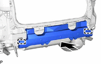
| | Install in this Direction |
11. INSTALL LOWER REAR BUMPER RETAINER LH
(a) Engage the claw as shown in the illustration.
| | Install in this Direction |
| (b) Install the lower rear bumper retainer LH with the 2 screws. |
|
.png)
12. INSTALL LOWER REAR BUMPER RETAINER RH
HINT:
Use the same procedure as for the LH side.
13. CONNECT REAR WHEEL HOUSE LINER LH
| (a) Connect the rear wheel house liner LH with the 2 screws and grommet. |
|
.png)
14. CONNECT REAR WHEEL HOUSE LINER RH
HINT:
Use the same procedure as for the LH side.
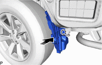
15. INSTALL REAR BUMPER SIDE RETAINER LH
(a) Engage the claw as shown in the illustration.
| | Install in this Direction |
(b) Engage the 3 clips as shown in the illustration to install the rear bumper side retainer LH.

| | Install in this Direction |
16. INSTALL REAR BUMPER SIDE RETAINER RH
HINT:
Use the same procedure as for the LH side.
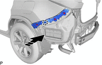
17. INSTALL REAR BUMPER EXTENSION RETAINER LH
| (a) Engage the guide, 2 claws and clip. |
|
.png)
(b) Install the rear bumper extension retainer LH with the 3 screws and 2 clips.
.png)
.png) | Screw |
.png) | Clip |
18. INSTALL REAR BUMPER EXTENSION RETAINER RH
HINT:
Use the same procedure as for the LH side.
19. INSTALL CENTER REAR BUMPER EXTENSION SUB-ASSEMBLY
(a) Engage the 3 clips.
.png)
(b) Install the center rear bumper extension sub-assembly with the 5 screws.
.png)
(c) for TMMC Made with Kick Sensor:
(1) Install the kick door control sensor with bracket.
except F-Sport:
Click here
for F-Sport:
Click here
20. INSTALL REFLEX REFLECTOR ASSEMBLY LH
| (a) Engage the guide and claw. |
|
.png)
| (b) Install the reflex reflector assembly LH with the screw. |
|
.png)
21. INSTALL REFLEX REFLECTOR ASSEMBLY RH
HINT:
Use the same procedure as for the LH side.
22. INSTALL REAR BUMPER EXTENSION SUB-ASSEMBLY LH
| (a) Install 4 new grommets. |
|
.png)
| (b) Install the rear bumper extension sub-assembly LH with the 4 screws. |
|
.png)
23. INSTALL REAR BUMPER EXTENSION SUB-ASSEMBLY RH
HINT:
Use the same procedure as for the LH side.
24. INSTALL NO. 1 MOULDING TAPE
HINT:
- Use the same procedure for the LH side and RH side.
- When installing the No. 1 moulding tape, heat the rear bumper assembly using a heat light.
Heating Temperature:
| Item | Temperature |
|---|---|
| Rear Bumper Assembly | 20 to 30°C (68 to 86°F) |
CAUTION:
- Do not touch the heat light and heated parts, touching the heat light may result in burns.
- Touching heated parts for a long time may result in burns.
.png)
| *a | Heated Part |
| *b | Heat Light |
NOTICE:
Do not heat the rear bumper assembly excessively.
(a) Clean the rear bumper assembly surface.
(1) Using a heat light, heat the rear bumper assembly surface.
(2) Remove the double-sided tape from the rear bumper assembly.
(3) Wipe off any tape adhesive residue with cleaner.
(b) Remove the release paper from a new No. 1 moulding tape.
HINT:
After removing the release paper, keep the exposed adhesive free from foreign matter.
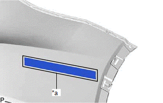
| (c) Install the No. 1 moulding tape as shown in the illustration. HINT: Press the No. 1 moulding tape firmly to install it. |
|
25. INSTALL ULTRASONIC SENSOR CLIP (w/o Intuitive Parking Assist System)
HINT:
When installing the ultrasonic sensor clip, heat the rear bumper assembly using a heat light.
Heating Temperature:
| Item | Temperature |
|---|---|
| Rear Bumper Assembly | 20 to 30°C (68 to 86°F) |
CAUTION:
- Do not touch the heat light and heated parts, touching the heat light may result in burns.
- Touching heated parts for a long time may result in burns.
| *a | Heated Part |
| *b | Heat Light |
NOTICE:
Do not heat the rear bumper assembly excessively.
(a) w/ Kick Sensor:
(1) Clean the rear bumper assembly surface.
- Using a heat light, heat the rear bumper assembly surface.
- Remove the double-sided tape from the rear bumper assembly.
- Wipe off any tape adhesive residue with cleaner.
(2) Using a brush or felt, apply primer or equivalent to the ultrasonic sensor clip installation area.
.png)
.png) | Primer |
(3) Remove the release paper from a new ultrasonic sensor clip.
HINT:
After removing the release paper, keep the exposed adhesive free from foreign matter.
(4) Install the 2 ultrasonic sensor clips as shown in the illustration.
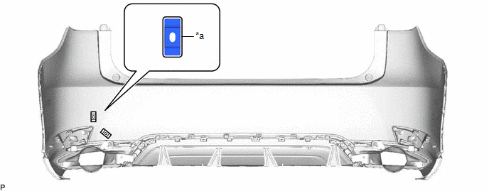
| *a | Line | - | - |
HINT:
Press the ultrasonic sensor clip firmly to install it.
26. INSTALL ULTRASONIC SENSOR CLIP (w/ Intuitive Parking Assist System)
HINT:
When installing the ultrasonic sensor clip, heat the rear bumper assembly using a heat light.
Heating Temperature:
| Item | Temperature |
|---|---|
| Rear Bumper Assembly | 20 to 30°C (68 to 86°F) |
CAUTION:
- Do not touch the heat light and heated parts, touching the heat light may result in burns.
- Touching heated parts for a long time may result in burns.
| *a | Heated Part |
| *b | Heat Light |
NOTICE:
Do not heat the rear bumper assembly excessively.
(a) Clean the rear bumper assembly surface.
(1) Using a heat light, heat the rear bumper assembly surface.
(2) Remove the double-sided tape from the rear bumper assembly.
(3) Wipe off any tape adhesive residue with cleaner.
(b) Using a brush or felt, apply primer or equivalent to the ultrasonic sensor clip installation area.
| | Primer |
(c) Remove the release paper from a new ultrasonic sensor clip.
HINT:
After removing the release paper, keep the exposed adhesive free from foreign matter.
(d) Install each ultrasonic sensor clip as shown in the illustration.
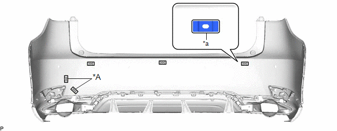
| *A | w/ Kick Sensor | - | - |
| *a | Line | - | - |
HINT:
Press the ultrasonic sensor clip firmly to install it.
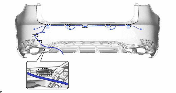
27. INSTALL NO. 3 LUGGAGE ROOM WIRE (w/o Intuitive Parking Assist System)
(a) for TMMC Made with Kick Sensor:
(1) Engage the 3 clamps to install the No. 3 luggage room wire.
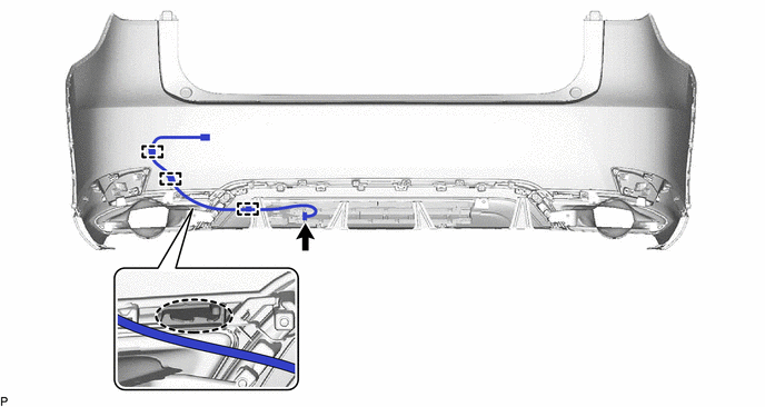
.png) | Rib | - | - |
HINT:
Pass the No. 3 luggage room wire under the rib as shown in the illustration.
(2) Connect the connector.
28. INSTALL NO. 3 LUGGAGE ROOM WIRE (w/ Intuitive Parking Assist System)
(a) for TMC Made without Kick Sensor:
(1) Engage the 5 clamps to install the No. 3 luggage room wire.
.png)
(b) for TMC Made with Kick Sensor:
(1) Engage the 7 clamps to install the No. 3 luggage room wire.
| | Rib | - | - |
HINT:
Pass the No. 3 luggage room wire under the rib as shown in the illustration.
(c) for TMMC Made with Kick Sensor:
(1) Engage the 8 clamps to install the No. 3 luggage room wire.
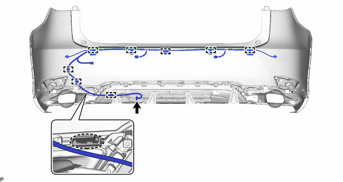
| | Rib | - | - |
HINT:
Pass the No. 3 luggage room wire under the rib as shown in the illustration.
(2) Connect the connector.
29. INSTALL KICK DOOR CONTROL SENSOR WITH BRACKET (for TMC Made with Kick Sensor)
except F-Sport:
Click here
for F-Sport:
Click here
30. INSTALL REAR CORNER ULTRASONIC SENSOR RETAINER (w/ Intuitive Parking Assist System)
Click here
31. INSTALL REAR CENTER ULTRASONIC SENSOR RETAINER (w/ Intuitive Parking Assist System)
Click here
32. INSTALL REAR CORNER ULTRASONIC SENSOR (w/ Intuitive Parking Assist System)
Click here
33. INSTALL REAR CENTER ULTRASONIC SENSOR (w/ Intuitive Parking Assist System)
Click here
 Installation
INSTALLATION PROCEDURE 1. INSTALL REAR BUMPER ASSEMBLY (a) w/ Intuitive Parking Assist System or Kick Sensor: (1) Connect the connector. (b) Engage the 2 claws as shown in the illustration. Ins ...

Other materials:
Lexus RX (RX 350L, RX450h) 2016-2026 Repair Manual > Camshaft Oil Control Solenoid (for Bank 1): Removal
REMOVAL CAUTION / NOTICE / HINT The necessary procedures (adjustment, calibration, initialization or registration) that must be performed after parts are removed and installed, or replaced during camshaft timing oil control solenoid assembly bolt removal/installation are shown below. Necessary Proce ...
Lexus RX (RX 350L, RX450h) 2016-2026 Repair Manual > Power Tilt And Power Telescopic Steering Column System: Fail-safe Chart
FAIL-SAFE CHART HINT: If the power source voltage to the multiplex tilt and telescopic ECU returns to normal within 10 seconds during tilt or telescopic operation, the operation will be resumed. If it returns to normal after 10 seconds have elapsed, the operation restarts when a tilt or telescopic o ...
Lexus RX (RX 350L, RX450h) 2016-{YEAR} Owners Manual
- For your information
- Pictorial index
- For safety and security
- Instrument cluster
- Operation of each component
- Driving
- Lexus Display Audio system
- Interior features
- Maintenance and care
- When trouble arises
- Vehicle specifications
- For owners
Lexus RX (RX 350L, RX450h) 2016-{YEAR} Repair Manual

0.0108