Lexus RX (RX 350L, RX450h) 2016-2026 Repair Manual: Removal
REMOVAL
CAUTION / NOTICE / HINT
The necessary procedures (adjustment, calibration, initialization or registration) that must be performed after parts are removed and installed, or replaced during camshaft timing oil control solenoid assembly bolt removal/installation are shown below.
Necessary Procedures After Parts Removed/Installed/Replaced| Replaced Part or Performed Procedure | Necessary Procedure | Effect/Inoperative Function when Necessary Procedure not Performed | Link |
|---|---|---|---|
| Battery terminal is disconnected/reconnected | Memorize steering angle neutral point | Lane Control System | |
| Pre-collision System | |||
| Intelligent Clearance Sonar System*1 | |||
| Parking Assist Monitor System | | ||
| Panoramic View Monitor System | | ||
| Lighting System (w/ Automatic Headlight Beam Level Control System) | | ||
| Initialize back door lock | Power Door Lock Control System | | |
| Reset back door close position | Power Back Door System (w/ Outside Door Control Switch) | | |
| Replacement of ECM | Vehicle Identification Number (VIN) registration | MIL comes on | |
| ECU Communication ID Registration (Immobiliser system) | Engine start function | | |
| Perform code registration (Immobiliser system) |
| | |
| Replacement of ECM (If possible, read the transaxle compensation code from the previous ECM) | Perform the following procedures in the order shown:
|
| |
| Replacement of ECM (If impossible, read the transaxle compensation code from the previous ECM) | Perform the following procedures in the order shown:
| ||
| Inspection After Repair |
| |
| Front wheel alignment adjustment | Calibration |
| |
| Suspension, tires, etc. (The vehicle height changes because of suspension or tire replacement) |
|
| |
| Rear television camera assembly optical axis (Back camera position setting) | Parking assist monitor system | for Initialization: for Calibration: | |
| Panoramic view monitor system | for Initialization: for Calibration: | |
| Initialize No. 1 headlight ECU sub-assembly LH | Lighting System (w/ Automatic Headlight Beam Level Control System) | |
*1: When performing learning using the Techstream.
Click here .gif)
PROCEDURE
1. REMOVE ENGINE ASSEMBLY WITH TRANSAXLE
Click here
2. REMOVE CAMSHAFT TIMING OIL CONTROL SOLENOID ASSEMBLY (for Intake Side of Bank 1)
| (a) Disconnect the camshaft timing oil control solenoid assembly connector. |
|
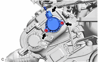
(b) Remove the 2 bolts and camshaft timing oil control solenoid assembly from the timing chain cover assembly.
NOTICE:
If the camshaft timing oil control solenoid assembly has been struck or dropped, replace it.
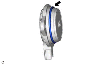
| (c) Remove the O-ring from the camshaft timing oil control solenoid assembly. NOTICE:
|
|
3. REMOVE CAMSHAFT TIMING OIL CONTROL SOLENOID ASSEMBLY (for Exhaust Side of Bank 1)
| (a) Disconnect the camshaft timing oil control solenoid assembly connector. |
|
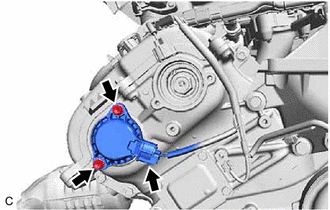
(b) Remove the 2 bolts and camshaft timing oil control solenoid assembly from the timing chain cover assembly.
NOTICE:
If the camshaft timing oil control solenoid assembly has been struck or dropped, replace it.
| (c) Remove the O-ring from the camshaft timing oil control solenoid assembly. NOTICE:
|
|
 On-vehicle Inspection
ON-VEHICLE INSPECTION PROCEDURE 1. INSPECT CAMSHAFT TIMING OIL CONTROL SOLENOID ASSEMBLY (a) Connect the Techstream to the DLC3. (b) Start the engine. (c) Turn the Techstream on. (d) Inspect the camsh ...
 Inspection
INSPECTION PROCEDURE 1. INSPECT CAMSHAFT TIMING OIL CONTROL SOLENOID ASSEMBLY HINT: Use the same procedure for the intake side and exhaust side. (a) Check the resistance. (1) Measure the resistance ...
Other materials:
Lexus RX (RX 350L, RX450h) 2016-2026 Repair Manual > Brake Master Cylinder: Disassembly
DISASSEMBLY PROCEDURE 1. REMOVE BRAKE MASTER CYLINDER TO WAY TUBE (a) Secure the brake master cylinder sub-assembly with way in a vise. NOTICE: Place aluminum plates on the vise to prevent damage to the brake master cylinder sub-assembly and No. 2 brake tube way. (b) Using a union nut wrench, rem ...
Lexus RX (RX 350L, RX450h) 2016-2026 Repair Manual > Power Window Control System: Problem Symptoms Table
PROBLEM SYMPTOMS TABLE NOTICE:
Before replacing the main body ECU (multiplex network body ECU), refer to Registration.
Click here HINT:
Use the table below to help determine the cause of problem symptoms. If multiple suspected areas are listed, the potential causes of the symptoms are l ...
Lexus RX (RX 350L, RX450h) 2016-{YEAR} Owners Manual
- For your information
- Pictorial index
- For safety and security
- Instrument cluster
- Operation of each component
- Driving
- Lexus Display Audio system
- Interior features
- Maintenance and care
- When trouble arises
- Vehicle specifications
- For owners
Lexus RX (RX 350L, RX450h) 2016-{YEAR} Repair Manual

0.0105