Lexus RX (RX 350L, RX450h) 2016-2026 Repair Manual: Installation
INSTALLATION
PROCEDURE
1. INSTALL REAR CENTER SEAT OUTER BELT ASSEMBLY
| (a) Engage the 2 guides and temporarily install the rear center seat outer belt assembly with the 2 nuts. |
|
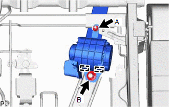
(b) Fully tighten the nut (A) and then the nut (B) to install rear center seat outer belt assembly.
Torque:
Nut (A) :
12.5 N·m {127 kgf·cm, 9 ft·lbf}
Nut (B) :
42 N·m {428 kgf·cm, 31 ft·lbf}
2. INSTALL REAR SEATBACK EDGE PROTECTOR
Click here .gif)
3. INSTALL SEPARATE TYPE REAR SEATBACK COVER WITH PAD
Click here
4. INSTALL REAR SEAT SHOULDER BELT COVER
Click here
5. INSTALL SEAT BELT ANCHOR COVER CAP
Click here
6. INSTALL RECLINING REMOTE CONTROL LEVER SUB-ASSEMBLY RH
Click here
7. INSTALL REAR SEAT UPPER RECLINING COVER RH
Click here
8. INSTALL REAR SEATBACK BOARD CARPET ASSEMBLY RH
Click here
9. INSTALL REAR SEATBACK COVER RH
Click here
10. CONNECT REAR CENTER SEAT OUTER BELT ASSEMBLY
(a) Connect the anchor of the rear center seat outer belt assembly with the bolt.
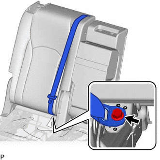
.png) | Protruding Part |
Torque:
42 N·m {428 kgf·cm, 31 ft·lbf}
NOTICE:
Do not allow the anchor part of the rear center seat outer belt assembly to overlap the protruding parts of the rear seatback frame sub-assembly.
11. INSTALL REAR NO. 1 SEAT RECLINING ADJUSTER INSIDE COVER
Click here
12. INSTALL SEPARATE TYPE REAR SEAT CUSHION COVER WITH PAD
Click here
13. INSTALL REAR SEAT LOCK CONTROL LEVER SUB-ASSEMBLY RH
Click here
14. INSTALL NO. 1 RECLINING ADJUSTER RELEASE HANDLE RH
Click here
15. INSTALL REAR SEAT COVER CAP RH
Click here
16. INSTALL REAR NO. 1 SEAT ASSEMBLY RH
Click here
 Removal
REMOVAL CAUTION / NOTICE / HINT The necessary procedures (adjustment, calibration, initialization or registration) that must be performed after parts are removed and installed, or replaced during rear ...

Other materials:
Lexus RX (RX 350L, RX450h) 2016-2026 Repair Manual > Headlight Assembly: Components
COMPONENTS ILLUSTRATION *1 FRONT FENDER REINFORCEMENT SUB-ASSEMBLY TOP *2 HEADLIGHT ASSEMBLY *3 CENTER HOOD CUSHION - - N*m (kgf*cm, ft.*lbf): Specified torque - - ILLUSTRATION *A w/ Automatic Headlight Beam Level Control System *B for Bulb Type Turn Signa ...
Lexus RX (RX 350L, RX450h) 2016-2026 Repair Manual > Sfi System: O2 Sensor Circuit Bank 1 Sensor 2 Circuit Short to Ground (P013611,...,P015623)
DESCRIPTION In order to obtain a high purification rate of the carbon monoxide (CO), hydrocarbon (HC) and nitrogen oxide (NOx) components in the exhaust gas, a TWC (Three-Way Catalytic Converter) is used. For the most efficient use of the TWC, the air fuel ratio must be precisely controlled so that ...
Lexus RX (RX 350L, RX450h) 2016-{YEAR} Owners Manual
- For your information
- Pictorial index
- For safety and security
- Instrument cluster
- Operation of each component
- Driving
- Lexus Display Audio system
- Interior features
- Maintenance and care
- When trouble arises
- Vehicle specifications
- For owners
Lexus RX (RX 350L, RX450h) 2016-{YEAR} Repair Manual

0.0127