
Lexus RX (RX 350L, RX450h) 2016-2026 Repair Manual: Driver Side Seat Belt Warning Light does not Operate
DESCRIPTION
The seat belt warning light on the combination meter assembly illuminates, blinks or turns off in accordance with the state of the front seat inner belt assembly LH.
WIRING DIAGRAM
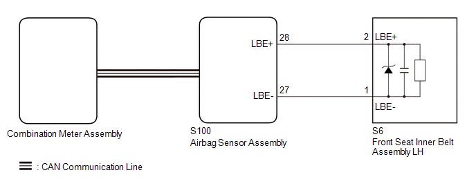
CAUTION / NOTICE / HINT
NOTICE:
-
The seat belt warning system uses the CAN communication system. First, confirm that there are no malfunctions in the CAN communication system. Refer to How to Proceed with Troubleshooting.
Click here
.gif)
PROCEDURE
| 1. | CHECK DTC OUTPUT (AIRBAG SYSTEM) |
(a) Clear the DTCs.
Click here
(b) Check for DTCs.
Click here
| Result | Proceed to |
|---|---|
| DTCs are not output | A |
| DTCs are output | B |
| B | .gif) | GO TO AIRBAG SYSTEM |
|
.gif)
| 2. | READ VALUE USING TECHSTREAM |
(a) Connect the Techstream to the DLC3.
(b) Turn the engine switch on (IG).
(c) Turn the Techstream on.
(d) Enter the following menus: Body Electrical / SRS Airbag / Data List.
(e) Read the Data List according to the display on the Techstream.
Body Electrical > SRS Airbag > Data List| Tester Display | Measurement Item | Range | Normal Condition | Diagnostic Note |
|---|---|---|---|---|
| Left side Buckle SW | LH buckle switch | Unset, Set or NG | Unset: Seat belt not fastened Set: Seat belt fastened NG: Data is not determined | - |
| Tester Display |
|---|
| Left side Buckle SW |
| Result | Proceed to |
|---|---|
| Unset or Set is displayed on the Techstream according to the driver seat belt condition | A |
| Unset or Set is not displayed correctly on the Techstream according to the driver seat belt condition | B |
| NG is displayed on the Techstream | C |
| A | | REPLACE COMBINATION METER ASSEMBLY |
| B | | REPLACE FRONT SEAT INNER BELT ASSEMBLY LH |
| C | | REPLACE AIRBAG SENSOR ASSEMBLY |
 On-vehicle Inspection
ON-VEHICLE INSPECTION PROCEDURE 1. INSPECT DRIVER SEAT BELT WARNING LIGHT HINT: The seat belt warning light on the combination meter assembly is used for both the driver seat and front passenger seat. ...
 Front Passenger Side Seat Belt Warning Light Malfunction
DESCRIPTION When the engine switch is turned on (IG), the occupant detection ECU sends signals to the airbag sensor assembly to indicate the state of the front seat inner belt assembly RH and also whe ...
Other materials:
Lexus RX (RX 350L, RX450h) 2016-2026 Repair Manual > Power Mirror Control System (w/ Memory): Reverse Shift-linked Function of Power Mirrors does not Operate
DESCRIPTION The ECM sends the reverse signal to the main body ECU (multiplex network body ECU) via CAN communication. When receiving the reverse signal, the main body ECU (multiplex network body ECU) sends the reverse request signal to each outer mirror control ECU assembly. Based on the signal, eac ...
Lexus RX (RX 350L, RX450h) 2016-2026 Repair Manual > Sfi System: Actuator Supply Voltage "A" Circuit Short to Ground or Open (P065714)
DESCRIPTION The electronic throttle control system has a dedicated power supply circuit. The voltage (+BM) is monitored and when it is low (less than 4 V), the ECM determines that there is a malfunction in the electronic throttle control system and cuts off the current to the throttle actuator. When ...
Lexus RX (RX 350L, RX450h) 2016-{YEAR} Owners Manual
- For your information
- Pictorial index
- For safety and security
- Instrument cluster
- Operation of each component
- Driving
- Lexus Display Audio system
- Interior features
- Maintenance and care
- When trouble arises
- Vehicle specifications
- For owners
Lexus RX (RX 350L, RX450h) 2016-{YEAR} Repair Manual

0.0121