Lexus RX (RX 350L, RX450h) 2016-2026 Repair Manual: Driver Side Seat Position Sensor (B1653)
DESCRIPTION
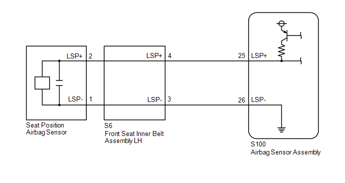
The seat position airbag sensor circuit consists of the airbag sensor assembly and seat position airbag sensor.
DTC B1653 is stored when a malfunction is detected in the seat position airbag sensor circuit.
| DTC No. | Detection Item | DTC Detection Condition | Trouble Area | Warning Indicate | Test Mode / Check Mode |
|---|---|---|---|---|---|
| B1653 | Driver Side Seat Position Sensor |
|
| Comes on | Does not apply to test/check mode |
WIRING DIAGRAM
CAUTION / NOTICE / HINT
NOTICE:
After turning the engine switch off, waiting time may be required before disconnecting the cable from the negative (-) battery terminal. Therefore, make sure to read the disconnecting the cable from the negative (-) battery terminal notices before proceeding with work.
Click here .gif)
PROCEDURE
| 1. | CHECK CONNECTION OF CONNECTORS |
(a) Turn the engine switch off.
(b) Disconnect the cable from the negative (-) battery terminal.
CAUTION:
Wait at least 90 seconds after disconnecting the cable from the negative (-) battery terminal to disable the SRS system.
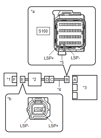
(c) Check that the connectors are properly connected to the airbag sensor assembly, front seat inner belt assembly LH and seat position airbag sensor.
OK:
The connectors are properly connected.
| NG | .gif) | CONNECT CONNECTORS PROPERLY |
|
.gif)
| 2. | CHECK CONNECTORS |
(a) Disconnect the connectors from the airbag sensor assembly, front seat inner belt assembly LH and seat position airbag sensor.
(b) Check that the terminals of the connectors are not deformed or damaged.
OK:
The terminals are not deformed or damaged.
| NG | | REPLACE NO. 2 FLOOR WIRE OR FRONT SEAT INNER BELT ASSEMBLY LH |
|
| 3. | CHECK WIRE HARNESS |
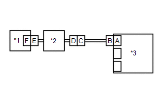
| (a) Connect the connectors to the front seat inner belt assembly LH and No. 2 floor wire. |
|
(b) Connect the cable to the negative (-) battery terminal.
(c) Turn the engine switch on (IG).
(d) Measure the voltage according to the value(s) in the table below.
Standard Voltage:
| Tester Connection | Condition | Specified Condition |
|---|---|---|
| 2 (LSP+) - Body ground | Engine switch on (IG) | Below 1 V |
| 1 (LSP-) - Body ground | Engine switch on (IG) | Below 1 V |
(e) Turn the engine switch off.
(f) Disconnect the cable from the negative (-) battery terminal.
CAUTION:
Wait at least 90 seconds after disconnecting the cable from the negative (-) battery terminal to disable the SRS system.
(g) Using a service wire, connect terminals 25 (LSP+) and 26 (LSP-) of connector B.
NOTICE:
Do not forcibly insert the service wire into the terminals of the connector when connecting the wire.
(h) Measure the resistance according to the value(s) in the table below.
Standard Resistance:
| Tester Connection | Condition | Specified Condition |
|---|---|---|
| 2 (LSP+) - 1 (LSP-) | Always | Below 1 Ω |
(i) Disconnect the service wire from connector B.
(j) Measure the resistance according to the value(s) in the table below.
Standard Resistance:
| Tester Connection | Condition | Specified Condition |
|---|---|---|
| 2 (LSP+) - 1 (LSP-) | Always | 1 MΩ or higher |
| 2 (LSP+) - Body ground | Always | 1 MΩ or higher |
| 1 (LSP-) - Body ground | Always | 1 MΩ or higher |
| NG | | GO TO STEP 6 |
|
| 4. | CHECK DTC |
| (a) Connect the connectors to the airbag sensor assembly and seat position airbag sensor. |
|
(b) Connect the cable to the negative (-) battery terminal.
(c) Turn the engine switch on (IG), and wait for at least 60 seconds.
(d) Clear the DTCs stored in memory.
Body Electrical > SRS Airbag > Clear DTCs(e) Turn the engine switch off.
(f) Turn the engine switch on (IG), and wait for at least 60 seconds.
(g) Check for DTCs.
Body Electrical > SRS Airbag > Trouble CodesOK:
DTC B1653 is not output.
HINT:
Codes other than DTC B1653 may be output at this time, but they are not related to this check.
| OK | | USE SIMULATION METHOD TO CHECK |
|
| 5. | CHECK SEAT POSITION AIRBAG SENSOR |
| (a) Turn the engine switch off. |
|
(b) Disconnect the cable from the negative (-) battery terminal.
CAUTION:
Wait at least 90 seconds after disconnecting the cable from the negative (-) battery terminal to disable the SRS system.
(c) Replace the seat position airbag sensor with a known good one.
Click here
HINT:
Perform the following inspection using known good parts from another vehicle if possible.
(d) Connect the cable to the negative (-) battery terminal.
(e) Turn the engine switch on (IG), and wait for at least 60 seconds.
(f) Clear the DTCs stored in memory.
Body Electrical > SRS Airbag > Clear DTCs(g) Turn the engine switch off.
(h) Turn the engine switch on (IG), and wait for at least 60 seconds.
(i) Check for DTCs.
Body Electrical > SRS Airbag > Trouble CodesOK:
DTC B1653 is not output.
HINT:
Codes other than DTC B1653 may be output at this time, but they are not related to this check.
(j) Turn the engine switch off.
(k) Disconnect the cable from the negative (-) battery terminal.
CAUTION:
Wait at least 90 seconds after disconnecting the cable from the negative (-) battery terminal to disable the SRS system.
(l) Restore the seat position airbag sensor that was installed for testing to its original location.
Click here
| OK | | REPLACE SEAT POSITION AIRBAG SENSOR |
| NG | | REPLACE AIRBAG SENSOR ASSEMBLY |
| 6. | CHECK NO. 2 FLOOR WIRE |
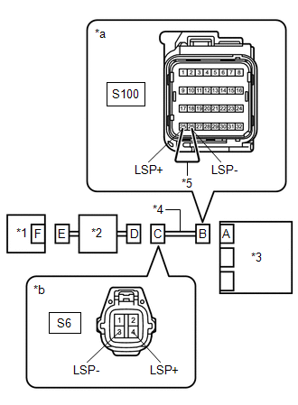
| (a) Disconnect the No. 2 floor wire connector from the front seat inner belt assembly LH. |
|
(b) Connect the cable to the negative (-) battery terminal.
(c) Turn the engine switch on (IG).
(d) Measure the voltage according to the value(s) in the table below.
Standard Voltage:
| Tester Connection | Condition | Specified Condition |
|---|---|---|
| S6-4 (LSP+) - Body ground | Engine switch on (IG) | Below 1 V |
| S6-3 (LSP-) - Body ground | Engine switch on (IG) | Below 1 V |
(e) Turn the engine switch off.
(f) Disconnect the cable from the negative (-) battery terminal.
CAUTION:
Wait at least 90 seconds after disconnecting the cable from the negative (-) battery terminal to disable the SRS system.
(g) Using a service wire, connect terminals 25 (LSP+) and 26 (LSP-) of connector B.
NOTICE:
Do not forcibly insert the service wire into the terminals of the connector when connecting the wire.
(h) Measure the resistance according to the value(s) in the table below.
Standard Resistance:
| Tester Connection | Condition | Specified Condition |
|---|---|---|
| S6-4 (LSP+) - S6-3 (LSP-) | Always | Below 1 Ω |
(i) Disconnect the service wire from connector B.
(j) Measure the resistance according to the value(s) in the table below.
Standard Resistance:
| Tester Connection | Condition | Specified Condition |
|---|---|---|
| S6-4 (LSP+) - S6-3 (LSP-) | Always | 1 MΩ or higher |
| S6-4 (LSP+) - Body ground | Always | 1 MΩ or higher |
| S6-3 (LSP-) - Body ground | Always | 1 MΩ or higher |
| OK | | REPLACE FRONT SEAT INNER BELT ASSEMBLY LH |
| NG | | REPLACE NO. 2 FLOOR WIRE |
 Occupant Classification System Malfunction (B1650,B165A)
DESCRIPTION The airbag sensor assembly and occupant detection ECU communicate via CAN communication. When the occupant detection ECU stores DTC B1771, B1780, B1782, B1795, B1798, B1799, U0125 or U0129 ...
 Seat Belt Buckle Switch (LH) (B1656)
DESCRIPTION The front seat belt buckle switch LH circuit consists of the airbag sensor assembly and front seat belt buckle switch LH (front seat inner belt assembly LH). DTC B1656 is stored when a mal ...
Other materials:
Lexus RX (RX 350L, RX450h) 2016-2026 Repair Manual > Panoramic View Monitor System: Driver Side Camera Video Sync Signal Malfunction (C1686)
DESCRIPTION This DTC is stored if the parking assist ECU judges as a result of its self check that a synchronization problem is occurring in the image signal sent from the driver side television camera assembly to the parking assist ECU. DTC No. Detection Item DTC Detection Condition Troubl ...
Lexus RX (RX 350L, RX450h) 2016-2026 Repair Manual > Front Door Lock: Installation
INSTALLATION CAUTION / NOTICE / HINT HINT:
Use the same procedure for the RH side and LH side.
The following procedure is for the LH side.
PROCEDURE 1. PRECAUTION NOTICE: After turning the engine switch off, waiting time may be required before disconnecting the cable from the negative (-) ba ...
Lexus RX (RX 350L, RX450h) 2016-{YEAR} Owners Manual
- For your information
- Pictorial index
- For safety and security
- Instrument cluster
- Operation of each component
- Driving
- Lexus Display Audio system
- Interior features
- Maintenance and care
- When trouble arises
- Vehicle specifications
- For owners
Lexus RX (RX 350L, RX450h) 2016-{YEAR} Repair Manual

0.0102