Lexus RX (RX 350L, RX450h) 2016-2026 Repair Manual: SRS Warning Light Remains ON
DESCRIPTION
The SRS warning light is located in the combination meter assembly.
When the SRS is normal, the SRS warning light comes on for approximately 6 seconds after the engine switch is turned from off to on (IG), and then turns off automatically.
If there is a malfunction in the SRS, the SRS warning light comes on to inform the driver of a problem.
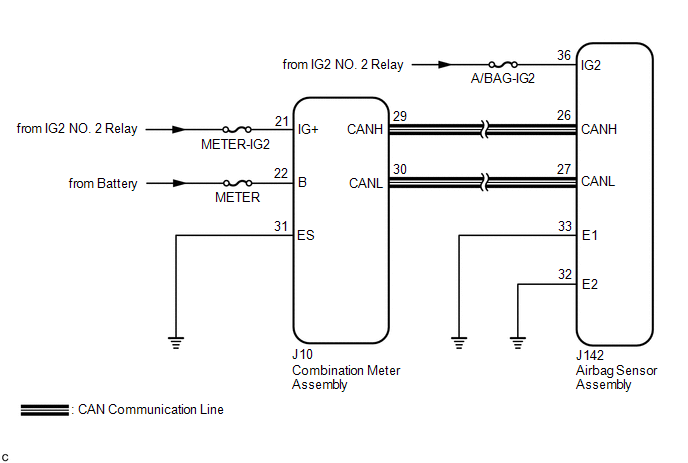
If a malfunction occurs in the airbag sensor assembly, combination meter assembly or wire harness connected to the airbag sensor assembly or combination meter assembly, the SRS warning light comes on.
The SRS is equipped with a voltage-increase circuit (DC-DC converter) in the airbag sensor assembly in case the power source voltage drops.
When the battery voltage drops, the voltage-increase circuit (DC-DC converter) functions to increase the voltage of the SRS to normal voltage. In addition, when the voltage drops, the SRS warning light will illuminate.
A malfunction in this circuit is not stored in the airbag sensor assembly. The SRS warning light automatically turns off when the power source voltage returns to normal.
The signal to illuminate the SRS warning light is transmitted from the airbag sensor assembly to the combination meter assembly via CAN communication.
WIRING DIAGRAM
CAUTION / NOTICE / HINT
NOTICE:
-
After turning the engine switch off, waiting time may be required before disconnecting the cable from the negative (-) battery terminal. Therefore, make sure to read the disconnecting the cable from the negative (-) battery terminal notices before proceeding with work.
Click here
.gif)
- Inspect the fuses for circuits related to this system before performing the following procedure.
PROCEDURE
| 1. | CHECK SRS WARNING LIGHT OPERATION |
(a) Turn the engine switch on (IG) and check the SRS warning light condition.
HINT:
The primary check is performed for approximately 6 seconds after the engine switch is turned on (IG).
| Result | Proceed to |
|---|---|
| After the primary check period, the SRS warning light remains on. | A |
| After the primary check period, the SRS warning light turns off and comes on again. | B |
| B | .gif) | GO TO STEP 6 |
|
.gif)
| 2. | CHECK BATTERY VOLTAGE |
(a) Measure the voltage of the battery.
Standard Voltage:
11 to 14 V
| NG | | INSPECT CHARGING SYSTEM AND BATTERY |
|
| 3. | CHECK CONNECTOR |
(a) Turn the engine switch off.
(b) Disconnect the cable from the negative (-) battery terminal.
CAUTION:
Wait at least 90 seconds after disconnecting the cable from the negative (-) battery terminal to disable the SRS system.
(c) Check that the connector is properly connected to the airbag sensor assembly.
OK:
The connector is properly connected.
HINT:
If the connector is not properly connected, reconnect the connector and proceed to the next inspection.
(d) Disconnect the connector from the airbag sensor assembly.
(e) Check that the terminals of the connector are not deformed or damaged.
OK:
The terminals are not deformed or damaged.
| NG | | REPLACE WIRE HARNESS |
|
| 4. | CHECK WIRE HARNESS (AIRBAG SENSOR ASSEMBLY - BODY GROUND) |
| (a) Connect the cable to the negative (-) battery terminal. |
|
(b) Turn the engine switch on (IG).
(c) Operate all components of the electrical systems (defogger, wipers, headlights, heater blower, etc.).
(d) Measure the voltage according to the value(s) in the table below.
Standard Voltage:
| Tester Connection | Condition | Specified Condition |
|---|---|---|
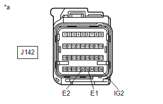
| J142-36 (IG2) - Body ground | Engine switch on (IG) | 8 to 16 V |
(e) Turn the engine switch off.
(f) Measure the resistance according to the value(s) in the table below.
Standard Resistance:
| Tester Connection | Condition | Specified Condition |
|---|---|---|
| J142-33 (E1) - Body ground | Always | Below 1 Ω |
| J142-32 (E2) - Body ground | Always | Below 1 Ω |
| NG | | REPLACE WIRE HARNESS |
|
| 5. | CHECK SRS WARNING LIGHT |
(a) Turn the engine switch on (IG) and check the SRS warning light condition.
OK:
After the primary check period, the SRS warning light turns off for approximately 10 seconds and then turns back on.
HINT:
The primary check period is approximately 6 seconds after the engine switch is turned on (IG).
| OK | | REPLACE AIRBAG SENSOR ASSEMBLY |
| NG | | REPLACE COMBINATION METER ASSEMBLY |
| 6. | CHECK CAN COMMUNICATION SYSTEM |
(a) Using the Techstream, check if the CAN communication system is functioning normally.
OK:
CAN communication system is functioning normally.
HINT:
Refer to Communication Bus Check in CAN Communication System.
Click here
| NG | | GO TO CAN COMMUNICATION SYSTEM |
|
| 7. | CHECK BATTERY VOLTAGE |
(a) Measure the voltage of the battery.
Standard Voltage:
11 to 14 V
| NG | | INSPECT CHARGING SYSTEM AND BATTERY |
|
| 8. | CHECK CONNECTOR |
(a) Turn the engine switch off.
(b) Disconnect the cable from the negative (-) battery terminal.
CAUTION:
Wait at least 90 seconds after disconnecting the cable from the negative (-) battery terminal to disable the SRS system.
(c) Check that the connector is properly connected to the airbag sensor assembly.
OK:
The connector is properly connected.
HINT:
If the connector is not properly connected, reconnect the connector and proceed to the next inspection.
(d) Disconnect the connector from the airbag sensor assembly.
(e) Check that the terminals of the connector are not deformed or damaged.
OK:
The terminals are not deformed or damaged.
| NG | | REPLACE WIRE HARNESS |
|
| 9. | CHECK WIRE HARNESS (AIRBAG SENSOR ASSEMBLY - BODY GROUND) |
| (a) Connect the cable to the negative (-) battery terminal. |
|
(b) Turn the engine switch on (IG).
(c) Operate all components of the electrical systems (defogger, wipers, headlights, heater blower, etc.).
(d) Measure the voltage according to the value(s) in the table below.
Standard Voltage:
| Tester Connection | Condition | Specified Condition |
|---|---|---|
| J142-36 (IG2) - Body ground | Engine switch on (IG) | 8 to 16 V |
(e) Turn the engine switch off.
(f) Measure the resistance according to the value(s) in the table below.
Standard Resistance:
| Tester Connection | Condition | Specified Condition |
|---|---|---|
| J142-33 (E1) - Body ground | Always | Below 1 Ω |
| J142-32 (E2) - Body ground | Always | Below 1 Ω |
| NG | | REPLACE WIRE HARNESS |
|
| 10. | CHECK CONNECTOR |
(a) Disconnect the cable from the negative (-) battery terminal.
CAUTION:
Wait at least 90 seconds after disconnecting the cable from the negative (-) battery terminal to disable the SRS system.
(b) Check that the connector is properly connected to the combination meter assembly.
OK:
The connector is properly connected.
HINT:
If the connector is not properly connected, reconnect the connector and proceed to the next inspection.
(c) Disconnect the connector from the combination meter assembly.
(d) Check that the terminals of the connector are not deformed or damaged.
OK:
The terminals are not deformed or damaged.
| NG | | REPAIR OR REPLACE CONNECTOR |
|
| 11. | CHECK WIRE HARNESS (COMBINATION METER ASSEMBLY - BODY GROUND) |
| (a) Connect the cable to the negative (-) battery terminal. |
|
(b) Turn the engine switch on (IG).
(c) Measure the voltage according to the value(s) in the table below.
Standard Voltage:
| Tester Connection | Condition | Specified Condition |
|---|---|---|
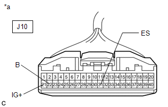
| J10-21 (IG+) - Body ground | Engine switch on (IG) | 11 to 14 V |
| J10-22 (B) - Body ground | Always | 11 to 14 V |
(d) Turn the engine switch off.
(e) Measure the resistance according to the value(s) in the table below.
Standard Resistance:
| Tester Connection | Condition | Specified Condition |
|---|---|---|
| J10-31 (ES) - Body ground | Always | Below 1 Ω |
| NG | | REPAIR OR REPLACE WIRE HARNESS |
|
| 12. | CHECK SRS WARNING LIGHT |
(a) Disconnect the cable from the negative (-) battery terminal.
CAUTION:
Wait at least 90 seconds after disconnecting the cable from the negative (-) battery terminal to disable the SRS system.
(b) Connect the connector to the combination meter assembly.
(c) Connect the cable to the negative (-) battery terminal.
(d) Turn the engine switch on (IG) and check the SRS warning light condition.
OK:
After the primary check period, the SRS warning light turns off for approximately 10 seconds and then turns back on.
HINT:
The primary check period is approximately 6 seconds after the engine switch is turned on (IG).
| OK | | REPLACE AIRBAG SENSOR ASSEMBLY |
| NG | | REPLACE COMBINATION METER ASSEMBLY |
 Lost Communication with Restraints Occupant Classification System Module (U0154)
DESCRIPTION The airbag sensor assembly sends/receives signals to/from each ECU via CAN communication. DTC No. Detection Item DTC Detection Condition Trouble Area Warning Indicate Test Mod ...

Other materials:
Lexus RX (RX 350L, RX450h) 2016-2026 Repair Manual > Wiper And Washer System: Dtc Check / Clear
DTC CHECK / CLEAR CHECK DTC (a) Connect the Techstream to the DLC3. (b) Turn the engine switch on (IG). (c) Turn the Techstream on. (d) Enter the following menus: Body Electrical / (desired system) / Trouble Codes. Body Electrical > Wiper > Trouble Codes Body Electrical > Rain Sensor > T ...
Lexus RX (RX 350L, RX450h) 2016-2026 Repair Manual > Seat Heater Switch (for Front Side): Installation
INSTALLATION PROCEDURE 1. INSTALL REFRESHING SEAT SWITCH (a) Engage the 4 claws to install the refreshing seat switch to the console panel sub-assembly. 2. INSTALL CONSOLE PANEL SUB-ASSEMBLY Click here 3. INSTALL INSTRUMENT CLUSTER FINISH PANEL ORNAMENT Click here 4. INSTALL SHIFT ...
Lexus RX (RX 350L, RX450h) 2016-{YEAR} Owners Manual
- For your information
- Pictorial index
- For safety and security
- Instrument cluster
- Operation of each component
- Driving
- Lexus Display Audio system
- Interior features
- Maintenance and care
- When trouble arises
- Vehicle specifications
- For owners
Lexus RX (RX 350L, RX450h) 2016-{YEAR} Repair Manual

0.0098