Lexus RX (RX 350L, RX450h) 2016-2026 Repair Manual: Terminals Of Ecu
TERMINALS OF ECU
CHECK ENGINE SWITCH

(a) Measure the voltage and resistance according to the value(s) in the table below.
| Terminal No. (Symbol) | Input/Output | Wiring Color | Terminal Description | Condition | Specified Condition | Related Data List Item/DTC |
|---|---|---|---|---|---|---|
| J14-6 (AGND) - Body ground | - | R - Body ground | Transponder key amplifier ground | Always | Below 1 Ω | - |
| J14-7 (TXCT) - J14-6 (AGND) | Input | L - R | Immobiliser communication input | Engine switch off, brake pedal not depressed, 30 seconds or more after driver door opened and then closed | Below 1 V | - |
| J14-8 (CODE) - J14-6 (AGND) | Output | G - R | Immobiliser communication output | Engine switch off, brake pedal not depressed, 30 seconds or more after driver door opened and then closed | Below 1 V | - |
| J14-10 (VC5) - J14-6 (AGND) | Input | R - R | Transponder key amplifier power supply | Engine switch off, brake pedal not depressed, 30 seconds or more after driver door opened and then closed | Below 1 V | - |
(b) Check for pulses according to the value(s) in the table below.
| Terminal No. (Symbol) | Input/Output | Wiring Color | Terminal Description | Condition | Specified Condition | Related Data List Item/DTC |
|---|---|---|---|---|---|---|
| J14-7 (TXCT) - J14-6 (AGND) | Input | L - R | Signal input from certification ECU (smart key ECU assembly) (Code sent from certification ECU (smart key ECU assembly) to transponder key amplifier built into engine switch, and then transmitted by transponder key amplifier antenna as radio waves) | Engine switch off, electrical key transmitter sub-assembly not in cabin, within 30 seconds of engine switch pressed | Pulse generation (See waveform 1) |
|
| J14-8 (CODE) - J14-6 (AGND) | Output | G - R | Signal output to certification ECU (smart key ECU assembly) (Radio waves from transponder key amplifier built into engine switch used to detect key information. Key information then sent to certification ECU (smart key ECU assembly)) | Engine switch off, engine switch pressed with electrical key transmitter sub-assembly held near engine switch* | Pulse generation (See waveform 2) | |
| J14-10 (VC5) - J14-6 (AGND) | Input | R - R | Transponder key amplifier power supply (Power supplied from certification ECU (smart key ECU assembly) when transponder key amplifier built into engine switch activated) | Engine switch off, electrical key transmitter sub-assembly not in cabin, within 30 seconds of engine switch pressed | Pulse generation (See waveform 3) |
HINT:
*: Remove the transmitter battery before performing this inspection.
(c) Using an oscilloscope, check the waveform.
NOTICE:
The waveform shown in the illustration is an example for reference only. Noise, chattering, etc. are not shown.
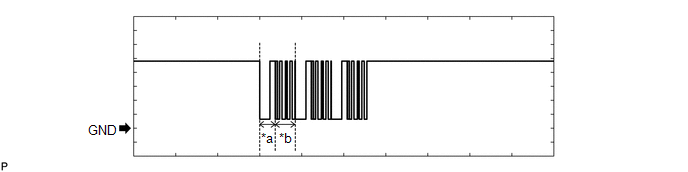
(1) Waveform 1 (Reference)
 Measurement Condition
 | Item | Content |
|---|---|
| Tester Connection | J14-7 (TXCT) - J14-6 (AGND) |
| Tool Setting | 2 V/DIV., 20 ms./DIV. |
| Condition | Engine switch off, electrical key transmitter sub-assembly not in cabin, within 30 seconds of engine switch pressed |
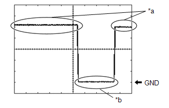
(2) Waveform 2 (Reference)
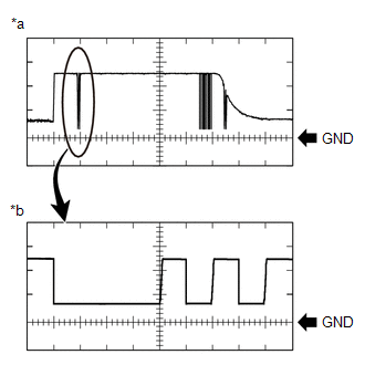
| *a | Waveform |
| *b | Waveform (detail) |
| Item | Content |
|---|---|
| Tester Connection | J14-8 (CODE) - J14-6 (AGND) |
| Tool Setting |
|
| Condition | Engine switch off, engine switch pressed with electrical key transmitter sub-assembly held near engine switch* |
HINT:
*: Remove the transmitter battery before performing this inspection.
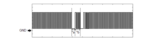
(3) Waveform 3 (Reference)
 Measurement Condition
 | Item | Content |
|---|---|
| Tester Connection | J14-10 (VC5) - J14-6 (AGND) |
| Tool Setting | 2 V/DIV., 200 ms./DIV. |
| Condition | Engine switch off, electrical key transmitter sub-assembly not in cabin, within 30 seconds of engine switch pressed |
CHECK CERTIFICATION ECU (SMART KEY ECU ASSEMBLY)
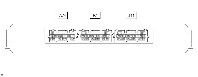
(a) Disconnect the J41 certification ECU (smart key ECU assembly) connector.
(b) Measure the voltage and resistance according to the value(s) in the table below.
| Terminal No. (Symbol) | Input/Output | Wiring Color | Terminal Description | Condition | Specified Condition | Related Data List Item/DTC |
|---|---|---|---|---|---|---|
| J41-4 (+B) - J41-18 (E) | Input | V - W-B | +B power supply | Always | 11 to 14 V | - |
| J41-18 (E) - Body ground | - | W-B - Body ground | Ground | Always | Below 1 Ω | - |
(c) Reconnect the J41 certification ECU (smart key ECU assembly) connector.
(d) Measure the voltage and resistance, and check for pulses according to the value(s) in the table below.
| Terminal No. (Symbol) | Input/Output | Wiring Color | Terminal Description | Condition | Specified Condition | Related Data List Item/DTC |
|---|---|---|---|---|---|---|
| J41-17 (IG1D) - J41-18 (E) | Output | G - W-B | Ignition power supply | Engine switch off | Below 1 V | - |
| Engine switch on (IG) | 11 to 14 V | - | ||||
| J41-5 (TXCT) - J41-11 (AGND) | Output | L - R | Signal output to transponder key amplifier | Engine switch off, brake pedal not depressed, 30 seconds or more after driver door opened and then closed | Below 1 V |
|
| J41-6 (CODE) - J41-11 (AGND) | Input | G - R | Signal input from transponder key amplifier | Engine switch off, brake pedal not depressed, 30 seconds or more after driver door opened and then closed | Below 1 V | |
| J41-7 (VC5) - J41-11 (AGND) | Output | R - R | Transponder key amplifier power supply | Engine switch off, brake pedal not depressed, 30 seconds or more after driver door opened and then closed | Below 1 V | |
| J41-11 (AGND) - Body ground | - | R - Body ground | Transponder key amplifier ground | Always | Below 1 Ω | |
| J41-20 (IND) - J41-18 (E) | Output | L - W-B | Security indicator output | Engine switch off → on (IG) | Pulse generation → Below 2 V | - |
(e) Check for pulses according to the value(s) in the table below.
| Terminal No. (Symbol) | Input/Output | Wiring Color | Terminal Description | Condition | Specified Condition | Related Data List Item/DTC |
|---|---|---|---|---|---|---|
| J41-5 (TXCT) - J41-11 (AGND) | Output | L - R | Signal output to transponder key amplifier (Code sent from certification ECU (smart key ECU assembly) to transponder key amplifier built into engine switch, and then transmitted by transponder key amplifier antenna as radio waves) | Engine switch off, electrical key transmitter sub-assembly not in cabin, within 30 seconds of engine switch pressed | Pulse generation (See waveform 1) |
|
| J41-6 (CODE) - J41-11 (AGND) | Input | G - R | Signal input from transponder key amplifier (Radio waves from transponder key amplifier built into engine switch used to detect key information. Key information then sent to certification ECU (smart key ECU assembly)) | Engine switch off, engine switch pressed with electrical key transmitter sub-assembly held near engine switch HINT: Remove the transmitter battery before performing this inspection. | Pulse generation (See waveform 2) | |
| J41-7 (VC5) - J41-11 (AGND) | Output | R - R | Transponder key amplifier power supply (Power supplied from certification ECU (smart key ECU assembly) when transponder key amplifier built into engine switch activated) | Engine switch off, electrical key transmitter sub-assembly not in cabin, within 30 seconds of engine switch pressed | Pulse generation (See waveform 3) |
(f) Using an oscilloscope, check the waveform.
NOTICE:
The waveform shown in the illustration is an example for reference only. Noise, chattering, etc. are not shown.
(1) Waveform 1 (Reference)
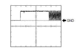 Measurement Condition
 | Item | Content |
|---|---|
| Tester Connection | J41-5 (TXCT) - J41-11 (AGND) |
| Tool Setting | 2 V/DIV., 20 ms./DIV. |
| Condition | Engine switch off, electrical key transmitter sub-assembly not in cabin, within 30 seconds of engine switch pressed |
(2) Waveform 2 (Reference)
| *a | Waveform |
| *b | Waveform (detail) |
| Item | Content |
|---|---|
| Tester Connection | J41-6 (CODE) - J41-11 (AGND) |
| Tool Setting |
|
| Condition | Engine switch off, engine switch pressed with electrical key transmitter sub-assembly held near engine switch* |
HINT:
*: Remove the transmitter battery before performing this inspection.
(3) Waveform 3 (Reference)
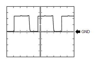 Measurement Condition
 | Item | Content |
|---|---|
| Tester Connection | J41-7 (VC5) - J41-11 (AGND) |
| Tool Setting | 2 V/DIV., 200 ms./DIV. |
| Condition | Engine switch off, electrical key transmitter sub-assembly not in cabin, within 30 seconds of engine switch pressed |
CHECK ID CODE BOX (IMMOBILISER CODE ECU)

(a) Disconnect the J36 ID code box (immobiliser code ECU) connector.
(b) Measure the voltage and resistance according to the value(s) in the table below.
| Terminal No. (Symbol) | Input/Output | Wiring Color | Terminal Description | Condition | Specified Condition | Related Data List Item/DTC |
|---|---|---|---|---|---|---|
| J36-1 (+B) - Body ground | Input | B - Body ground | +B power supply | Always | 11 to 14 V | B2789 |
| J36-5 (GND) - Body ground | - | B - Body ground | Ground | Always | Below 1 Ω | B2789 |
(c) Reconnect the J36 ID code box (immobiliser code ECU) connector.
(d) Measure the voltage and check for pulses according to the value(s) in the table below.
| Terminal No. (Symbol) | Input/Output | Wiring Color | Terminal Description | Condition | Specified Condition | Related Data List Item/DTC |
|---|---|---|---|---|---|---|
| J36-3 (EFII) - J36-5 (GND) | Input | B - B | EFI communication input (Signal input from ECM to ID code box (immobiliser code ECU)) | Engine switch off | 11 to 14 V |
|
| J36-4 (EFIO) - J36-5 (GND) | Output | B - B | EFI communication output (Signal output from ID code box (immobiliser code ECU) to ECM) | Engine switch off | 11 to 14 V | |
| J36-3 (EFII) - J36-5 (GND) | Input | B - B | EFI communication input (Signal input from ECM to ID code box (immobiliser code ECU)) | Within 3 seconds of engine start or within 3 seconds of engine switch turned on (IG) after cable disconnected and reconnected to battery | Pulse generation (See waveform 1) | |
| J36-4 (EFIO) - J36-5 (GND) | Output | B - B | EFI communication output (Signal output from ID code box (immobiliser code ECU) to ECM) | Engine switch turned on (IG) using registered electrical key transmitter sub-assembly | Pulse generation (See waveform 2) |
(e) Using an oscilloscope, check the waveform.
NOTICE:
The waveform shown in the illustration is an example for reference only. Noise, chattering, etc. are not shown.
(1) Waveform 1 (Reference)
| *a | Approximately 160 ms. | *b | Approximately 270 ms. |
| Item | Content |
|---|---|
| Tester Connection | J36-3 (EFII) - J36-5 (GND) |
| Tool Setting | 2 V/DIV., 500 ms./DIV. |
| Condition | Within 3 seconds of engine start or within 3 seconds of engine switch turned on (IG) after cable disconnected and reconnected to battery |
(2) Waveform 2 (Reference)
| *a | Approximately 160 ms. | *b | Approximately 270 ms. |
| Item | Content |
|---|---|
| Tester Connection | J36-4 (EFIO) - J36-5 (GND) |
| Tool Setting | 2 V/DIV., 500 ms./DIV. |
| Condition | Engine switch turned on (IG) using registered electrical key transmitter sub-assembly |
CHECK STEERING LOCK ECU (STEERING LOCK ACTUATOR OR UPPER BRACKET ASSEMBLY)

(a) Measure the voltage and resistance, and check for pulses according to the value(s) in the table below.
| Terminal No. (Symbol) | Input/Output | Wiring Color | Terminal Description | Condition | Specified Condition | Related Data List Item/DTC |
|---|---|---|---|---|---|---|
| L1-1 (GND) - Body ground | - | W-B - Body ground | Ground | Always | Below 1 Ω | - |
| L1-3 (IGE) - L1-1 (GND) | Input | SB - W-B | Steering lock motor operation permission signal (motor operation permission signal supplied by certification ECU (smart key ECU assembly)) | Steering lock motor operating when all conditions met, and then door opened:
| Pulse generation (See waveform 1) |
|
| L1-4 (SLP1) - L1-1 (GND) | Output | GR - W-B | Steering lock bar position signal (signal output from steering unlock sensor) | Steering locked → unlocked* | 11 to 14 V → Below 1.5 V | Sensor Value |
| L1-6 (IG2) - L1-1 (GND) | Input | P - W-B | IG signal (IG2 power supply input for steering lock motor) | Engine switch off | Below 1 V | B2788 |
| Engine switch on (IG) | 11 to 14 V | |||||
| L1-7 (B) - Body ground | Input | V - Body ground | Constant power supply | Always | 11 to 14 V | B2788 |
HINT:
*: The steering locks when any door is opened with the shift lever in P and the engine switch off. The steering unlocks when the engine switch is turned on (ACC).
(b) Using an oscilloscope, check the waveform.
NOTICE:
The waveform shown in the illustration is an example for reference only. Noise, chattering, etc. are not shown.
(1) Waveform 1 (Reference)
| *a | Steering lock motor not operating |
| *b | Steering lock motor operating |
| Item | Content |
|---|---|
| Tester Connection | L1-3 (IGE) - L1-1 (GND) |
| Tool Setting | 2 V/DIV., 200 ms./DIV. |
| Condition | Steering lock motor operating when all conditions met, and then door opened:
|
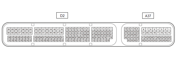
CHECK ECM
(a) Measure the voltage and resistance, and check for pulses according to the value(s) in the table below.
| Terminal No. (Symbol) | Input/Output | Wiring Color | Terminal Description | Condition | Specified Condition | Related Data List Item/DTC |
|---|---|---|---|---|---|---|
| A37-3 (+B2) - D2-53 (E1) | Input | L - BR | Ignition power supply | Engine switch on (IG) | 11 to 14 V | - |
| A37-2 (+B) - D2-53 (E1) | Input | R - BR | Ignition power supply | Engine switch on (IG) | 11 to 14 V | - |
| A37-46 (MREL) - D2-51 (E01) | Input | Y - W-B | Ignition power supply | Engine switch on (IG) | 11 to 14 V | - |
| A37-1 (BATT) - D2-53 (E1) | Input | G - BR | +B power supply | Always | 11 to 14 V | - |
| D2-51 (E01) - Body ground | - | W-B - Body ground | Ground | Always | Below 1 Ω | - |
| D2-53 (E1) - Body ground | - | BR - Body ground | Ground | Always | Below 1 Ω | - |
| D2-20 (E02) - Body ground | - | W-B - Body ground | Ground | Always | Below 1 Ω | - |
| A37-45 (IMO) - D2-53 (E1) | Output | G - BR | ID code box (immobiliser code ECU) communication output | Engine switch off | 11 to 14 V | - |
| A37-45 (IMO) - D2-53 (E1) | Output | G - BR | ID code box (immobiliser code ECU) communication output | Within 3 seconds of engine start or within 3 seconds of engine switch turned on (IG) after cable disconnected and reconnected to battery | Pulse generation (See waveform 1) | - |
| A37-59 (IMI) - D2-53 (E1) | Input | L - BR | ID code box (immobiliser code ECU) communication input | Engine switch off | 11 to 14 V | - |
| A37-59 (IMI) - D2-53 (E1) | Input | L - BR | ID code box (immobiliser code ECU) communication input | Engine switch turned on (IG) using registered electrical key transmitter sub-assembly | Pulse generation (See waveform 2) | - |
(b) Using an oscilloscope, check the waveform.
NOTICE:
The waveform shown in the illustration is an example for reference only. Noise, chattering, etc. are not shown.
(1) Waveform 1 (Reference)
| *a | Approximately 160 ms. | *b | Approximately 270 ms. |
| Item | Content |
|---|---|
| Tester Connection | A37-45 (IMO) - D2-53 (E1) |
| Tool Setting | 2 V/DIV., 500 ms./DIV. |
| Condition | Within 3 seconds of engine start or within 3 seconds of engine switch turned on (IG) after cable disconnected and reconnected to battery |
(2) Waveform 2 (Reference)
| *a | Approximately 160 ms. | *b | Approximately 270 ms. |
| Item | Content |
|---|---|
| Tester Connection | A37-59 (IMI) - D2-53 (E1) |
| Tool Setting | 2 V/DIV., 500 ms./DIV. |
| Condition | Engine switch turned on (IG) using registered electrical key transmitter sub-assembly |
 Dtc Check / Clear
DTC CHECK / CLEAR NOTICE: When using the Techstream with the engine switch off, connect the Techstream to the DLC3 and turn a courtesy light switch on and off at intervals of 1.5 seconds or less until ...
 Engine Starter Communication Malfunction (B2779)
DESCRIPTION If the remote engine start ECU does not respond to the certification ECU (smart key ECU assembly) or the remote engine start ID is not registered, this DTC is stored. HINT: Registration st ...
Other materials:
Lexus RX (RX 350L, RX450h) 2016-2026 Repair Manual > Sliding Roof Housing (for Slidng Roof): Removal
REMOVAL CAUTION / NOTICE / HINT The necessary procedures (adjustment, calibration, initialization or registration) that must be performed after parts are removed and installed, or replaced during sliding roof glass sub-assembly, sliding roof housing sub-assembly, sliding roof drive gear sub-assembly ...
Lexus RX (RX 350L, RX450h) 2016-2026 Repair Manual > Power Mirror Control System (w/o Memory): Driver Side Power Mirror cannot be Adjusted with Power Mirror Switch
DESCRIPTION The multiplex network master switch assembly sends the mirror adjust switch signals to the main body ECU (multiplex network body ECU) via LIN communication. The main body ECU (multiplex network body ECU) then sends the received mirror adjust switch signals to the outer mirror control ECU ...
Lexus RX (RX 350L, RX450h) 2016-{YEAR} Owners Manual
- For your information
- Pictorial index
- For safety and security
- Instrument cluster
- Operation of each component
- Driving
- Lexus Display Audio system
- Interior features
- Maintenance and care
- When trouble arises
- Vehicle specifications
- For owners
Lexus RX (RX 350L, RX450h) 2016-{YEAR} Repair Manual

0.0116