Lexus RX (RX 350L, RX450h) 2016-2026 Repair Manual: ACC Monitor Malfunction (B2274)
DESCRIPTION
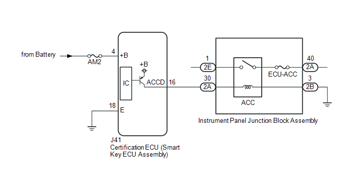
This DTC is stored when a malfunction in the ACC output circuit is detected. The ACC output circuit is the circuit between terminal ACCD of the certification ECU (smart key ECU assembly) and the ACC relay.
| DTC No. | Detection Item | DTC Detection Condition | Trouble Area | Note |
|---|---|---|---|---|
| B2274 | ACC Monitor Malfunction | The ACC relay circuit of the certification ECU (smart key ECU assembly) is malfunctioning. (1-trip detection logic*) HINT: When the voltage at terminal ACCD is not at the standard, the system is determined to be malfunctioning. |
|
|
- *: Only detected while a malfunction is present.
| Vehicle Condition when Malfunction Detected | Fail-safe Function when Malfunction Detected |
|---|---|
HINT: The engine switch can be turned on (IG) and the engine can be started. | - |
| DTC No. | Data List and Active Test |
|---|---|
| B2274 | Power Source Control
Starting Control
|
WIRING DIAGRAM
CAUTION / NOTICE / HINT
NOTICE:
- When using the Techstream with the engine switch off, connect the Techstream to the DLC3 and turn a courtesy light switch on and off at intervals of 1.5 seconds or less until communication between the Techstream and the vehicle begins. Then select the vehicle type under manual mode and enter the following menus: Body Electrical / Smart Access. While using the Techstream, periodically turn a courtesy light switch on and off at intervals of 1.5 seconds or less to maintain communication between the Techstream and the vehicle.
-
The smart access system with push-button start (for Start Function) uses the LIN communication system and CAN communication system. Inspect the communication function by following How to Proceed with Troubleshooting. Troubleshoot the smart access system with push-button start (for Start Function) after confirming that the communication systems are functioning properly.
Click here
.gif)
- Inspect the fuses of circuits related to this system before performing the following procedure.
-
Before replacing the certification ECU (smart key ECU assembly), refer to the smart access system with push-button start (for Start Function) Precaution.
Click here
- After repair, confirm that no DTCs are output by performing "DTC Output Confirmation Operation".
HINT:
When the cable is disconnected and reconnected to the negative (-) battery terminal, the power source mode returns to the state it was in before the cable was disconnected.
PROCEDURE
| 1. | CHECK HARNESS AND CONNECTOR (POWER SOURCE) |
Click here
| NG | .gif) | REPAIR OR REPLACE HARNESS OR CONNECTOR IN CIRCUIT CONNECTED TO POWER SOURCE |
|
.gif)
| 2. | CHECK HARNESS AND CONNECTOR (GROUND) |
Click here
| NG | | REPAIR OR REPLACE HARNESS OR CONNECTOR |
|
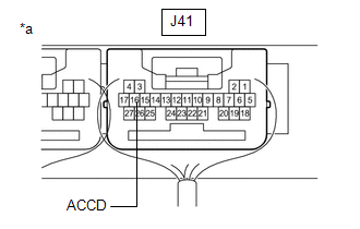
| 3. | CHECK HARNESS AND CONNECTOR (CERTIFICATION ECU (SMART KEY ECU ASSEMBLY) - INSTRUMENT PANEL JUNCTION BLOCK ASSEMBLY) |
(a) Disconnect the 2A and 2B instrument panel junction block assembly connector.
(b) Measure the resistance according to the value(s) in the table below.
Standard Resistance:
| Tester Connection | Condition | Specified Condition |
|---|---|---|
| J41-16 (ACCD) - 2A-30 | Always | Below 1 Ω |
| 2B-3 - Body ground | Always | Below 1 Ω |
| J41-16 (ACCD) or 2A-30 - Body ground | Always | 10 kΩ or higher |
| NG | | REPAIR OR REPLACE HARNESS OR CONNECTOR |
|
| 4. | CHECK INSTRUMENT PANEL JUNCTION BLOCK ASSEMBLY (ACC RELAY) |
(a) Remove the instrument panel junction block assembly.
Click here
(b) Measure the resistance according to the value(s) in the table below.
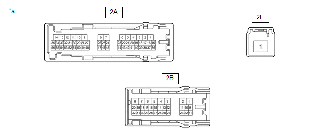
| *a | Component without harness connected (Instrument Panel Junction Block Assembly) | - | - |
Standard Resistance:
| Tester Connection | Condition | Specified Condition |
|---|---|---|
| 2A-30 - 2B-3 | 20°C (68°F) | 285.71 to 428.57 Ω |
| 2E-1 - 2A-40 | Battery voltage not applied between terminals 2A-30 and 2B-3 | 10 kΩ or higher |
| Battery voltage not applied between terminals 2A-30 and 2B-3 | Below 1 Ω |
| NG | | REPLACE INSTRUMENT PANEL JUNCTION BLOCK ASSEMBLY |
|
| 5. | CHECK CERTIFICATION ECU (SMART KEY ECU ASSEMBLY) |
| (a) Reconnect the J41 certification ECU (smart key ECU assembly) connector. |
|
(b) Install the instrument panel junction block assembly.
Click here
(c) Measure the voltage according to the value(s) in the table below.
Standard Voltage:
| Tester Connection | Condition | Specified Condition |
|---|---|---|
| J41-16 (ACCD) - Body ground | Engine switch off → Engine switch on (ACC) | 1 V or less → 8.5 V or higher |
| OK | | END (TEMPORARY CONNECTION FAILURE IS SUSPECTED) |
| NG | | REPLACE CERTIFICATION ECU (SMART KEY ECU ASSEMBLY) |
 Ignition Hold Monitor Malfunction (B2271)
DESCRIPTION This DTC is stored when a malfunction in the IG circuit or IG hold circuit of the certification ECU (smart key ECU assembly) is detected. DTC No. Detection Item DTC Detection Condit ...
 Detecting Vehicle Submersion (B2277)
DESCRIPTION This DTC is stored when a malfunction in the water submersion detection circuit inside the certification ECU (smart key ECU assembly) is detected. DTC No. Detection Item DTC Detecti ...
Other materials:
Lexus RX (RX 350L, RX450h) 2016-2026 Repair Manual > Sfi System: HO2S Heater Control Circuit Bank 1 Sensor 2 Circuit Short to Battery (P003612,P003614,P005612,P005614,P014118,P016118,P102A9E,P105A9E)
DESCRIPTION Refer to DTC P013611. Click here HINT:
When any of these DTCs are stored, the ECM enters fail-safe mode. The ECM turns off the heated oxygen sensor heater in fail-safe mode. Fail-safe mode continues until the engine switch is turned off.
The heated oxygen sensor heater circuit us ...
Lexus RX (RX 350L, RX450h) 2016-2026 Repair Manual > Power Tilt And Power Telescopic Steering Column System: Terminals Of Ecu
TERMINALS OF ECU MULTIPLEX TILT AND TELESCOPIC ECU *a Component without harness connected (Multiplex Tilt and Telescopic ECU) - - (a) Measure the voltage and resistance according to the value(s) in the table below. Terminal No. (Symbol) Wiring Color Terminal Description Conditi ...
Lexus RX (RX 350L, RX450h) 2016-{YEAR} Owners Manual
- For your information
- Pictorial index
- For safety and security
- Instrument cluster
- Operation of each component
- Driving
- Lexus Display Audio system
- Interior features
- Maintenance and care
- When trouble arises
- Vehicle specifications
- For owners
Lexus RX (RX 350L, RX450h) 2016-{YEAR} Repair Manual

0.0134