Lexus RX (RX 350L, RX450h) 2016-2026 Repair Manual: Engine/Power Switch Malfunction (B2278)
DESCRIPTION
This DTC is stored when the SSW1 contact signal and SSW2 contact signal, which are detected when the engine switch is operated, do not match.
| DTC No. | Detection Item | DTC Detection Condition | Trouble Area | Note |
|---|---|---|---|---|
| B2278 | Engine/Power Switch Malfunction | When the engine switch is operated, the SSW1 contact signal and SSW2 contact signal do not match (1-trip detection logic*). |
|
|
- *: Only detected while a malfunction is present.
| Vehicle Condition when Malfunction Detected | Fail-safe Function when Malfunction Detected |
|---|---|
| If either the SSW1 contact signal or SSW2 contact signal is stuck on, the power source mode cannot be changed by pressing the engine switch. If either the SSW1 contact signal or SSW2 contact signal is stuck off, emergency stop by pressing and holding the engine switch for 2 seconds or more cannot be operated. | - |
| DTC No. | Data List and Active Test |
|---|---|
| B2278 | Power Source Control
|
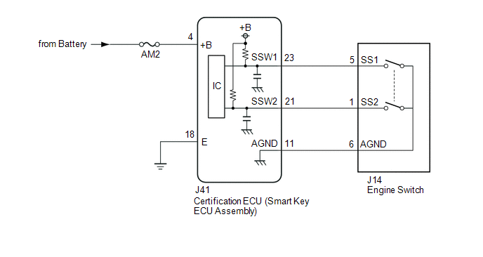
WIRING DIAGRAM
CAUTION / NOTICE / HINT
NOTICE:
- When using the Techstream with the engine switch off, connect the Techstream to the DLC3 and turn a courtesy light switch on and off at intervals of 1.5 seconds or less until communication between the Techstream and the vehicle begins. Then select the vehicle type under manual mode and enter the following menus: Body Electrical / Smart Access. While using the Techstream, periodically turn a courtesy light switch on and off at intervals of 1.5 seconds or less to maintain communication between the Techstream and the vehicle.
-
The smart access system with push-button start (for Start Function) uses the LIN communication system and CAN communication system. Inspect the communication function by following How to Proceed with Troubleshooting. Troubleshoot the smart access system with push-button start (for Start Function) after confirming that the communication systems are functioning properly.
Click here
.gif)
- Inspect the fuses of circuits related to this system before performing the following procedure.
-
Before replacing the certification ECU (smart key ECU assembly), refer to smart access system with push-button start (for Start Function) Precaution.
Click here
- After repair, confirm that no DTCs are output by performing "DTC Output Confirmation Operation".
HINT:
When the cable is disconnected and reconnected to the negative (-) battery terminal, the power source mode returns to the state it was in before the cable was disconnected.
PROCEDURE
| 1. | READ VALUE USING TECHSTREAM (START SWITCH1, START SWITCH2) |
(a) Connect the Techstream to the DLC3.
(b) Turn the engine switch on (IG).
(c) Turn the Techstream on.
(d) Enter the following menus: Body Electrical / Power Source Control / Data List.
(e) Read the Data List according to the display on the Techstream.
Body Electrical > Power Source Control > Data List| Tester Display | Measurement Item | Range | Normal Condition | Diagnostic Note |
|---|---|---|---|---|
| Start Switch1 | Engine switch 1 status | OFF or ON | OFF: Engine switch not pressed ON: Engine switch pressed |
|
| Start Switch2 | Engine switch 2 status | OFF or ON | OFF: Engine switch not pressed ON: Engine switch pressed |
|
| Tester Display |
|---|
| Start Switch1 |
| Start Switch2 |
OK:
The Techstream display changes correctly in response to the engine switch operation.
| NG | .gif) | GO TO STEP 3 |
|
.gif)
| 2. | READ VALUE USING TECHSTREAM (START SWITCH1, START SWITCH2) |
(a) Connect the Techstream to the DLC3.
(b) Turn the engine switch on (IG).
(c) Turn the Techstream on.
(d) Enter the following menus: Body Electrical / Power Source Control / Data List.
(e) According to the display on the Techstream, read the Data List while wiggling the wire harness.
Body Electrical > Power Source Control > Data List| Tester Display | Measurement Item | Range | Normal Condition | Diagnostic Note |
|---|---|---|---|---|
| Start Switch1 | Engine switch 1 status | OFF or ON | OFF: Engine switch not pressed ON: Engine switch pressed |
|
| Start Switch2 | Engine switch 2 status | OFF or ON | OFF: Engine switch not pressed ON: Engine switch pressed |
|
| Tester Display |
|---|
| Start Switch1 |
| Start Switch2 |
OK:
The Techstream display changes correctly in response to the engine switch operation.
| OK | | USE SIMULATION METHOD TO CHECK |
| NG | | REPAIR OR REPLACE HARNESS OR CONNECTOR |
| 3. | CHECK HARNESS AND CONNECTOR (POWER SOURCE) |
Click here
| NG | | REPAIR OR REPLACE HARNESS OR CONNECTOR |
|
| 4. | CHECK HARNESS AND CONNECTOR (GROUND) |
Click here
| NG | | REPAIR OR REPLACE HARNESS OR CONNECTOR |
|
| 5. | CHECK HARNESS AND CONNECTOR (CERTIFICATION ECU (SMART KEY ECU ASSEMBLY) - ENGINE SWITCH) |
(a) Disconnect the J14 engine switch connector.
(b) Measure the resistance according to the value(s) in the table below.
Standard Resistance:
| Tester Connection | Condition | Specified Condition |
|---|---|---|
| J41-23 (SSW1) - J14-5 (SS1) | Always | Below 1 Ω |
| J41-21 (SSW2) - J14-1 (SS2) | Always | Below 1 Ω |
| J41-11 (AGND) - J14-6 (AGND) | Always | Below 1 Ω |
| J41-23 (SSW1) or J14-5 (SS1) - Body ground | Always | 10 kΩ or higher |
| J41-21 (SSW2) or J14-1 (SS2) - Body ground | Always | 10 kΩ or higher |
| J41-11 (AGND) or J14-6 (AGND) - Body ground | Always | 10 kΩ or higher |
| NG | | REPAIR OR REPLACE HARNESS OR CONNECTOR |
|
| 6. | INSPECT ENGINE SWITCH |
(a) Remove the engine switch.
Click here
(b) Inspect the engine switch.
Click here
| OK | | REPLACE CERTIFICATION ECU (SMART KEY ECU ASSEMBLY) |
| NG | | REPLACE ENGINE SWITCH |
 Detecting Vehicle Submersion (B2277)
DESCRIPTION This DTC is stored when a malfunction in the water submersion detection circuit inside the certification ECU (smart key ECU assembly) is detected. DTC No. Detection Item DTC Detecti ...
 Vehicle Speed Signal Malfunction (B2282,B2283)
DESCRIPTION DTC B2282 is stored when the vehicle speed signal sent by the combination meter assembly via direct line and the vehicle speed signal sent via CAN communication do not match. DTC B2283 is ...
Other materials:
Lexus RX (RX 350L, RX450h) 2016-2026 Repair Manual > Panoramic View Monitor System: Back Camera Feedback Malfunction (C1622)
DESCRIPTION DTC C1622 is stored if the parking assist ECU judges as a result of its self check that the signals or signal lines between the parking assist ECU and the rear television camera assembly are not normal. DTC No. Detection Item DTC Detection Condition Trouble Area C1622 Back ...
Lexus RX (RX 350L, RX450h) 2016-2026 Repair Manual > Navigation Antenna: Inspection
INSPECTION PROCEDURE 1. INSPECT NAVIGATION ANTENNA ASSEMBLY (w/o Manual (SOS) Switch) (a) Check that the navigation antenna assembly cable is properly installed and does not have any sharp bends, pinching or loose connections. (b) Current consumption check: (1) Measure the current consumption acc ...
Lexus RX (RX 350L, RX450h) 2016-{YEAR} Owners Manual
- For your information
- Pictorial index
- For safety and security
- Instrument cluster
- Operation of each component
- Driving
- Lexus Display Audio system
- Interior features
- Maintenance and care
- When trouble arises
- Vehicle specifications
- For owners
Lexus RX (RX 350L, RX450h) 2016-{YEAR} Repair Manual

0.0104