Lexus RX (RX 350L, RX450h) 2016-2026 Repair Manual: Vehicle Speed Signal Malfunction (B2282,B2283)
DESCRIPTION
DTC B2282 is stored when the vehicle speed signal sent by the combination meter assembly via direct line and the vehicle speed signal sent via CAN communication do not match.
DTC B2283 is stored when a malfunction in the vehicle speed sensor is detected.
| DTC No. | Detection Item | DTC Detection Condition | Trouble Area | Note |
|---|---|---|---|---|
| B2282 | Vehicle Speed Signal Malfunction | The vehicle speed signal sent by the combination meter assembly via direct line and the vehicle speed signal sent via CAN communication do not match. (1-trip detection logic*) |
|
|
| B2283 | Vehicle Speed Sensor Malfunction | Either of the of the following malfunctions is detected (a vehicle speed sensor malfunction is detected) (1-trip detection logic*):
|
| DTC Output Confirmation Operation:
|
- *: Only detected while a malfunction is present and the engine switch is on (IG).
| DTC Code | Vehicle Condition when Malfunction Detected | Fail-safe Function when Malfunction Detected |
|---|---|---|
| B2282 |
| - |
| B2283 |
| Steering lock motor operation is prohibited. |
| DTC No. | Data List and Active Test |
|---|---|
| B2282 B2283 | Power Source Control
Starting Control
Combination Meter
|
WIRING DIAGRAM
CAUTION / NOTICE / HINT
NOTICE:
- When using the Techstream with the engine switch off, connect the Techstream to the DLC3 and turn a courtesy light switch on and off at intervals of 1.5 seconds or less until communication between the Techstream and the vehicle begins. Then select the vehicle type under manual mode and enter the following menus: Body Electrical / Smart Access. While using the Techstream, periodically turn a courtesy light switch on and off at intervals of 1.5 seconds or less to maintain communication between the Techstream and the vehicle.
-
The smart access system with push-button start (for Start Function) uses the LIN communication system and CAN communication system. Inspect the communication function by following How to Proceed with Troubleshooting. Troubleshoot the smart access system with push-button start (for Start Function) after confirming that the communication systems are functioning properly.
Click here
.gif)
- Inspect the fuses of circuits related to this system before performing the following procedure.
-
Before replacing the certification ECU (smart key ECU assembly), refer to the smart access system with push-button start (for Start Function) Precaution.
Click here
- After repair, confirm that no DTCs are output by performing "DTC Output Confirmation Operation".
HINT:
When the cable is disconnected and reconnected to the negative (-) battery terminal, the power source mode returns to the state it was in before the cable was disconnected.
PROCEDURE
| 1. | READ VALUE USING TECHSTREAM (VEHICLE SPEED METER) |
(a) Connect the Techstream to the DLC3.
(b) Turn the engine switch on (IG).
(c) Turn the Techstream on.
(d) Enter the following menus: Body Electrical / Combination Meter / Data List.
(e) Read the Data List according to the display on the Techstream.
Body Electrical > Combination Meter > Data List| Tester Display | Measurement Item | Range | Normal Condition | Diagnostic Note |
|---|---|---|---|---|
| Vehicle Speed Meter | Vehicle speed | Min.: 0, Max.: 255 | Almost same as actual vehicle speed (Speedometer tester) | - |
| Tester Display |
|---|
| Vehicle Speed Meter |
HINT:
Using a speedometer tester, check the actual vehicle speed and the vehicle speed displayed on the Techstream.
OK:
Vehicle speed displayed on the Techstream is almost the same as the actual vehicle speed measured using a speedometer tester.
| NG | .gif) | GO TO METER / GAUGE SYSTEM (Speedometer Malfunction) |
|
.gif)
| 2. | READ VALUE USING TECHSTREAM (VEHICLE SPEED SIGNAL) |
(a) Enter the following menus: Body Electrical / Power Source Control / Data List.
(b) Read the Data List according to the display on the Techstream.
Body Electrical > Power Source Control > Data List| Tester Display | Measurement Item | Range | Normal Condition | Diagnostic Note |
|---|---|---|---|---|
| Vehicle Speed Signal | Vehicle being driven or stopped | Stop or Run | Stop: Vehicle stopped Run: Vehicle being driven at 5 km/h (3 mph) or more | - |
| Tester Display |
|---|
| Vehicle Speed Signal |
OK:
The Techstream display changes correctly in response to the vehicle condition.
| OK | | GO TO METER / GAUGE SYSTEM (HOW TO PROCEED WITH TROUBLESHOOTING) |
|
| 3. | CHECK HARNESS AND CONNECTOR (POWER SOURCE) |
Click here
| NG | | REPAIR OR REPLACE HARNESS OR CONNECTOR IN CIRCUIT CONNECTED TO POWER SOURCE |
|
| 4. | CHECK HARNESS AND CONNECTOR (GROUND) |
Click here
| NG | | REPAIR OR REPLACE HARNESS OR CONNECTOR |
|
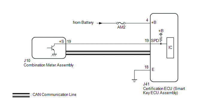
| 5. | CHECK HARNESS AND CONNECTOR (CERTIFICATION ECU (SMART KEY ECU ASSEMBLY) - COMBINATION METER ASSEMBLY) |
(a) Disconnect the J10 combination meter assembly connector.
(b) Measure the resistance according to the value(s) in the table below.
Standard Resistance:
| Tester Connection | Condition | Specified Condition |
|---|---|---|
| J41-19 (SPD) - J10-19 (+S) | Always | Below 1 Ω |
| J41-19 (SPD) or J10-19 (+S) - Body ground | Always | 10 kΩ or higher |
| NG | | REPAIR OR REPLACE HARNESS OR CONNECTOR |
|
| 6. | CHECK CERTIFICATION ECU (SMART KEY ECU ASSEMBLY) |
(a) Reconnect the J41 certification ECU (smart key ECU assembly) connector.
(b) Reconnect the J10 combination meter assembly connector.
(c) Using an oscilloscope, check the waveform.
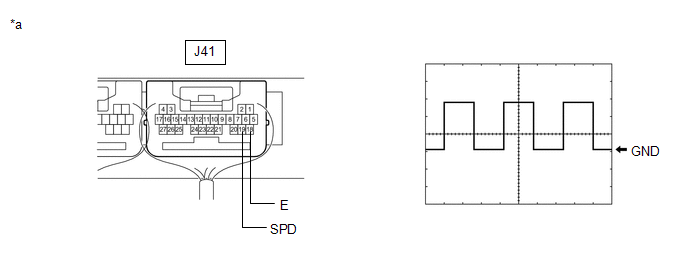
| *a | Component with harness connected (Certification ECU (Smart Key ECU Assembly)) | - | - |
| Tester Connection | Condition | Tool Setting | Specified Condition |
|---|---|---|---|
| J41-19 (SPD) - J41-18 (E) | Engine switch on (IG), vehicle being driven at approx. 5 km/h (3 mph) | 5 V/DIV., 20 ms./DIV. | Pulse generation |
HINT:
The wavelength becomes shorter as the vehicle speed increases.
| OK | | REPLACE CERTIFICATION ECU (SMART KEY ECU ASSEMBLY) |
| NG | | GO TO METER / GAUGE SYSTEM (Speed Signal Circuit) |
 Engine/Power Switch Malfunction (B2278)
DESCRIPTION This DTC is stored when the SSW1 contact signal and SSW2 contact signal, which are detected when the engine switch is operated, do not match. DTC No. Detection Item DTC Detection Co ...
 Brake Signal Malfunction (B2284)
DESCRIPTION This DTC is stored when the brake signal sent via direct line and the brake signal sent via CAN communication do not match. DTC No. Detection Item DTC Detection Condition Trouble ...
Other materials:
Lexus RX (RX 350L, RX450h) 2016-2026 Repair Manual > Audio And Visual System (for 12.3 Inch Display): Noise Occurs or Sound Skips when Portable Player Plays
CAUTION / NOTICE / HINT HINT:
Perform this check with the portable player volume set at an appropriate level.
Make sure that there are no obstructions between the portable player and radio receiver assembly that may block signals, and that the portable player and radio receiver assembly are not ...
Lexus RX (RX 350L, RX450h) 2016-2026 Repair Manual > Rear Power Seat Control System(for Second Row): Park / Neutral Position Switch Circuit
DESCRIPTION The fold seat control ECU receives switch operation signals, the back door courtesy light switch assembly signal*1, rear door courtesy light switch assembly signal*2 and driving condition signal and operates the rear power seat according these signals.
*1: When using fold seat switch ...
Lexus RX (RX 350L, RX450h) 2016-{YEAR} Owners Manual
- For your information
- Pictorial index
- For safety and security
- Instrument cluster
- Operation of each component
- Driving
- Lexus Display Audio system
- Interior features
- Maintenance and care
- When trouble arises
- Vehicle specifications
- For owners
Lexus RX (RX 350L, RX450h) 2016-{YEAR} Repair Manual

0.0113