Lexus RX (RX 350L, RX450h) 2016-2026 Repair Manual: Brake Signal Malfunction (B2284)
DESCRIPTION
This DTC is stored when the brake signal sent via direct line and the brake signal sent via CAN communication do not match.
| DTC No. | Detection Item | DTC Detection Condition | Trouble Area | Note |
|---|---|---|---|---|
| B2284 | Brake Signal Malfunction | The brake signal sent via direct line and the brake signal sent via CAN communication do not match. (1-trip detection logic*) |
|
|
- *: Only detected while a malfunction is present and the engine switch is on (IG).
| Vehicle Condition when Malfunction Detected | Fail-safe Function when Malfunction Detected |
|---|---|
| With the electrical key transmitter sub-assembly in the cabin, even if an engine start operation is performed, the engine does not start (the key indicator display is not displayed on the multi-information display). However, the engine can be started by turning the engine switch on (ACC) and then pressing and holding it.
| - |
| DTC No. | Data List and Active Test |
|---|---|
| B2284 | Power Source Control
Engine
|
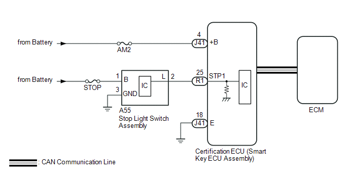
WIRING DIAGRAM
CAUTION / NOTICE / HINT
NOTICE:
- When using the Techstream with the engine switch off, connect the Techstream to the DLC3 and turn a courtesy light switch on and off at intervals of 1.5 seconds or less until communication between the Techstream and the vehicle begins. Then select the vehicle type under manual mode and enter the following menus: Body Electrical / Smart Access. While using the Techstream, periodically turn a courtesy light switch on and off at intervals of 1.5 seconds or less to maintain communication between the Techstream and the vehicle.
-
The smart access system with push-button start (for Start Function) uses the LIN communication system and CAN communication system. Inspect the communication function by following How to Proceed with Troubleshooting. Troubleshoot the smart access system with push-button start (for Start Function) after confirming that the communication systems are functioning properly.
Click here
.gif)
- Inspect the fuses of circuits related to this system before performing the following procedure.
-
Before replacing the certification ECU (smart key ECU assembly), refer to the smart access system with push-button start (for Start Function) Precaution.
Click here
- After repair, confirm that no DTCs are output by performing "DTC Output Confirmation Operation".
HINT:
When the cable is disconnected and reconnected to the negative (-) battery terminal, the power source mode returns to the state it was in before the cable was disconnected.
PROCEDURE
| 1. | READ VALUE USING TECHSTREAM (STOP LIGHT SWITCH1) |
(a) Connect the Techstream to the DLC3.
(b) Turn the engine switch on (IG).
(c) Turn the Techstream on.
(d) Enter the following menus: Body Electrical / Power Source Control / Data List.
(e) Read the Data List according to the display on the Techstream.
Body Electrical > Power Source Control > Data List| Tester Display | Measurement Item | Range | Normal Condition | Diagnostic Note |
|---|---|---|---|---|
| Stop Light Switch1 | State of brake pedal | OFF or ON | OFF: Brake pedal released ON: Brake pedal depressed |
|
| Tester Display |
|---|
| Stop Light Switch1 |
OK:
The Techstream display changes correctly in response to the brake pedal operation.
| OK | .gif) | GO TO SFI SYSTEM (HOW TO PROCEED WITH TROUBLESHOOTING) |
|
.gif)
| 2. | CHECK HARNESS AND CONNECTOR (POWER SOURCE) |
Click here
| NG | | REPAIR OR REPLACE HARNESS OR CONNECTOR IN CIRCUIT CONNECTED TO POWER SOURCE |
|
| 3. | CHECK HARNESS AND CONNECTOR (GROUND) |
Click here
| NG | | REPAIR OR REPLACE HARNESS OR CONNECTOR |
|
| 4. | CHECK HARNESS AND CONNECTOR (CERTIFICATION ECU (SMART KEY ECU ASSEMBLY) - STOP LIGHT SWITCH ASSEMBLY) |
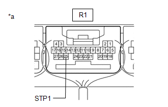
(a) Disconnect the R1 certification ECU (smart Key ECU assembly) connector.
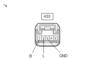
(b) Disconnect the A55 stop light switch assembly connector.
| (c) Measure the voltage according to the value(s) in the table below. Standard Voltage:
|
|
(d) Measure the resistance according to the value(s) in the table below.
Standard Resistance:
| Tester Connection | Condition | Specified Condition |
|---|---|---|
| R1-25 (STP1) - A55-2 (L) | Always | Below 1 Ω |
| A55-3 (GND) - Body ground | Always | Below 1 Ω |
| NG | | REPAIR OR REPLACE HARNESS OR CONNECTOR |
|
| 5. | CHECK CERTIFICATION ECU (SMART KEY ECU ASSEMBLY) |
(a) Reconnect the J41 and R1 certification ECU (smart Key ECU assembly) connectors.
(b) Reconnect the A55 stop light switch assembly connector.
| (c) Measure the voltage according to the value(s) in the table below. Standard Voltage:
|
|
| OK | | REPLACE CERTIFICATION ECU (SMART KEY ECU ASSEMBLY) |
| NG | | REPLACE STOP LIGHT SWITCH ASSEMBLY |
 Vehicle Speed Signal Malfunction (B2282,B2283)
DESCRIPTION DTC B2282 is stored when the vehicle speed signal sent by the combination meter assembly via direct line and the vehicle speed signal sent via CAN communication do not match. DTC B2283 is ...
 Steering Lock Position Signal Circuit Malfunction (B2285)
DESCRIPTION This DTC is stored when the steering lock position signal sent by the steering lock ECU (steering lock actuator or upper bracket assembly) via direct line and the steering lock position si ...
Other materials:
Lexus RX (RX 350L, RX450h) 2016-2026 Repair Manual > Automatic Transaxle Unit: Inspection
INSPECTION PROCEDURE 1. INSPECT TRANSMISSION OIL CLEANER MAGNET (a) Use the removed transmission oil cleaner magnets to collect any steel chips. Examine the chips and particles in the transaxle housing and on the transmission oil cleaner magnets to determine what type of wear might be found in th ...
Lexus RX (RX 350L, RX450h) 2016-2026 Repair Manual > Smart Access System With Push-button Start (for Entry Function): Open in Inside Luggage Compartment Electrical Key Oscillator Circuit (B27A7)
DESCRIPTION The certification ECU (smart key ECU assembly) generates a request signal and transmits the signal to the No. 3 indoor electrical key antenna assembly (inside luggage compartment). For the No. 3 indoor electrical key antenna assembly (inside luggage compartment) to detect when the electr ...
Lexus RX (RX 350L, RX450h) 2016-{YEAR} Owners Manual
- For your information
- Pictorial index
- For safety and security
- Instrument cluster
- Operation of each component
- Driving
- Lexus Display Audio system
- Interior features
- Maintenance and care
- When trouble arises
- Vehicle specifications
- For owners
Lexus RX (RX 350L, RX450h) 2016-{YEAR} Repair Manual

0.0113