Lexus RX (RX 350L, RX450h) 2016-2026 Repair Manual: Steering Lock Position Signal Circuit Malfunction (B2285)
DESCRIPTION
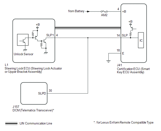
This DTC is stored when the steering lock position signal sent by the steering lock ECU (steering lock actuator or upper bracket assembly) via direct line and the steering lock position signal sent via LIN communication do not match.
| DTC No. | Detection Item | DTC Detection Condition | Trouble Area | Note |
|---|---|---|---|---|
| B2285 | Steering Lock Position Signal Circuit Malfunction | The steering lock position signal sent by the steering lock ECU (steering lock actuator or upper bracket assembly) via direct line and the steering lock position signal sent via LIN communication do not match. (1-trip detection logic*1) |
|
|
- *1: Only detected while a malfunction is present and the engine switch is on (IG).
- *2: for Lexus Enform Remote Compatible Type
| Vehicle Condition when Malfunction Detected | Fail-safe Function when Malfunction Detected |
|---|---|
| The engine cannot be started. | The ECU does not send an engine start request. |
| DTC No. | Data List and Active Test |
|---|---|
| B2285 | Power Source Control
Smart Access
|
WIRING DIAGRAM
CAUTION / NOTICE / HINT
NOTICE:
- When using the Techstream with the engine switch off, connect the Techstream to the DLC3 and turn a courtesy light switch on and off at intervals of 1.5 seconds or less until communication between the Techstream and the vehicle begins. Then select the vehicle type under manual mode and enter the following menus: Body Electrical / Smart Access. While using the Techstream, periodically turn a courtesy light switch on and off at intervals of 1.5 seconds or less to maintain communication between the Techstream and the vehicle.
-
The smart access system with push-button start (for Start Function) uses the LIN communication system and CAN communication system. Inspect the communication function by following How to Proceed with Troubleshooting. Troubleshoot the smart access system with push-button start (for Start Function) after confirming that the communication systems are functioning properly.
Click here
.gif)
- Inspect the fuses of circuits related to this system before performing the following procedure.
-
Before replacing the certification ECU (smart key ECU assembly), steering lock ECU (steering lock actuator or upper bracket assembly) or DCM (telematics transceiver)*, refer to the smart access system with push-button start (for Start Function) Precaution.
Click here
- After repair, confirm that no DTCs are output by performing "DTC Output Confirmation Operation".
- *: for LEXUS ENFORM Remote Compatible Type
HINT:
When the cable is disconnected and reconnected to the negative (-) battery terminal, the power source mode returns to the state it was in before the cable was disconnected.
PROCEDURE
| 1. | CHECK FOR DTC |
(a) Check for DTCs.
Body Electrical > Smart Access > Trouble CodesHINT:
- If the steering cannot be unlocked, the engine switch cannot be turned on (IG) and the engine cannot be started.
- If LIN communication is not available, the steering cannot be locked or unlocked.
OK:
LIN communication system DTC B2785 is not output simultaneously.
| NG | .gif) | GO TO DTC B2785 |
|
.gif)
| 2. | READ VALUE USING TECHSTREAM (STEERING UNLOCK SWITCH) |
(a) Connect the Techstream to the DLC3.
(b) Turn the engine switch on (IG).
(c) Turn the Techstream on.
(d) Enter the following menus: Body Electrical / Power Source Control / Data List.
(e) Read the Data List according to the display on the Techstream.
Body Electrical > Power Source Control > Data List| Tester Display | Measurement Item | Range | Normal Condition | Diagnostic Note |
|---|---|---|---|---|
| Steering Unlock Switch | State of steering unlock sensor signal output from steering lock ECU (steering lock actuator or upper bracket assembly) | OFF or ON | OFF: Steering locked ON: Steering unlocked |
|
| Tester Display |
|---|
| Steering Unlock Switch |
| Result | Proceed to |
|---|---|
| Techstream display does not change | A |
| Techstream display changes | B |
| B | | REPLACE STEERING LOCK ECU (STEERING LOCK ACTUATOR OR UPPER BRACKET ASSEMBLY) |
|
| 3. | CHECK HARNESS AND CONNECTOR (POWER SOURCE) |
Click here
| NG | | REPAIR OR REPLACE HARNESS OR CONNECTOR IN CIRCUIT CONNECTED TO POWER SOURCE |
|
| 4. | CHECK HARNESS AND CONNECTOR (GROUND) |
Click here
| NG | | REPAIR OR REPLACE HARNESS OR CONNECTOR |
|
| 5. | INSPECT STEERING LOCK ECU (STEERING LOCK ACTUATOR OR UPPER BRACKET ASSEMBLY) |
(a) Reconnect the J41 certification ECU (smart key ECU assembly) connector.
| (b) Measure the resistance according to the value(s) in the table below. Standard Resistance:
HINT:
|
| ||||||||||||
| Result | Proceed to |
|---|---|
| OK (except Lexus Enform Remote Compatible Type) | A |
| OK (for Lexus Enform Remote Compatible Type) | B |
| NG | C |
| B | | GO TO STEP 7 |
| C | | REPLACE STEERING LOCK ECU (STEERING LOCK ACTUATOR OR UPPER BRACKET ASSEMBLY) |
|
| 6. | CHECK HARNESS AND CONNECTOR (CERTIFICATION ECU (SMART KEY ECU ASSEMBLY) - STEERING LOCK ECU (STEERING LOCK ACTUATOR OR UPPER BRACKET ASSEMBLY)) |
(a) Disconnect the J41 certification ECU (smart key ECU assembly) connector.
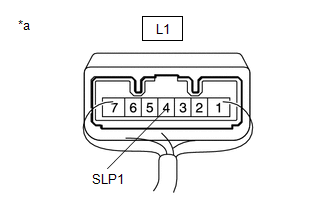
(b) Disconnect the L1 steering lock ECU (steering lock actuator or upper bracket assembly) connector.
(c) Measure the resistance according to the value(s) in the table below.
Standard Resistance:
| Tester Connection | Condition | Specified Condition |
|---|---|---|
| J41-14 (SLP) - L1-4 (SLP1) | Always | Below 1 Ω |
| J41-14 (SLP) or L1-4 (SLP1) - Body ground | Always | 10 kΩ or higher |
| OK | | REPLACE CERTIFICATION ECU (SMART KEY ECU ASSEMBLY) |
| NG | | REPAIR OR REPLACE HARNESS OR CONNECTOR |
| 7. | CHECK HARNESS AND CONNECTOR (CERTIFICATION ECU (SMART KEY ECU ASSEMBLY) - STEERING LOCK ECU (STEERING LOCK ACTUATOR OR UPPER BRACKET ASSEMBLY) - DCM) |
(a) Disconnect the J41 certification ECU (smart key ECU assembly) connector.
(b) Disconnect the L1 steering lock ECU (steering lock actuator or upper bracket assembly) connector.
(c) Disconnect the J157 DCM (telematics transceiver) connector.
(d) Measure the resistance according to the value(s) in the table below.
Standard Resistance:
| Tester Connection | Condition | Specified Condition |
|---|---|---|
| J41-14 (SLP) - L1-4 (SLP1) | Always | Below 1 Ω |
| L1-4 (SLP1) - J157-30 (SLPD) | Always | Below 1 Ω |
| J41-14 (SLP), L1-4 (SLP1) or J157-30 (SLPD) - Body ground | Always | 10 kΩ or higher |
(e) Measure the voltage according to the value(s) in the table below.
Standard Voltage:
| Tester Connection | Condition | Specified Condition |
|---|---|---|
| J41-14 (SLP), L1-4 (SLP1) or J157-30 (SLPD) - Body ground | Steering locked | 11 to 14 V |
| Steering unlocked | Below 1.5 V |
| NG | | REPAIR OR REPLACE HARNESS OR CONNECTOR |
|
| 8. | INSPECT CERTIFICATION ECU (SMART KEY ECU ASSEMBLY) |
(a) Check the push-button start function.
(1) Enter the vehicle while carrying an electrical key transmitter sub-assembly.
(2) Depress the brake pedal with the shift lever in P.
(3) Check that the engine starts when the engine switch is pressed.
| Result | Proceed to |
|---|---|
| Engine starts | A |
| Engine does not start | B |
| A | | REPLACE DCM (TELEMATICS TRANSCEIVER) |
| B | | REPLACE CERTIFICATION ECU (SMART KEY ECU ASSEMBLY) |
 Brake Signal Malfunction (B2284)
DESCRIPTION This DTC is stored when the brake signal sent via direct line and the brake signal sent via CAN communication do not match. DTC No. Detection Item DTC Detection Condition Trouble ...
 Runnable Signal Malfunction (B2286,P0335)
DESCRIPTION These DTCs are stored when the engine speed signal sent by the ECM via direct line and the engine speed signal sent via CAN communication do not match. DTC No. Detection Item DTC De ...
Other materials:
Lexus RX (RX 350L, RX450h) 2016-2026 Repair Manual > Lighting System (w/ Automatic Headlight Beam Level Control System): Taillight Relay Circuit
DESCRIPTION The main body ECU (multiplex network body ECU) controls the operation of the TAIL relay. WIRING DIAGRAM CAUTION / NOTICE / HINT NOTICE:
Inspect the fuses for circuits related to this system before performing the following procedure.
Before replacing the main body ECU (multiplex net ...
Lexus RX (RX 350L, RX450h) 2016-2026 Repair Manual > Immobiliser System: Engine Immobiliser System Incorrect Assembly (B279C95)
DESCRIPTION If an ECM that is incompatible with the immobiliser system is installed, the ECM will store this DTC. DTC No. Detection Item DTC Detection Condition Trouble Area Note B279C95 Engine Immobiliser System Incorrect Assembly An ECM that is incompatible with the immobiliser ...
Lexus RX (RX 350L, RX450h) 2016-{YEAR} Owners Manual
- For your information
- Pictorial index
- For safety and security
- Instrument cluster
- Operation of each component
- Driving
- Lexus Display Audio system
- Interior features
- Maintenance and care
- When trouble arises
- Vehicle specifications
- For owners
Lexus RX (RX 350L, RX450h) 2016-{YEAR} Repair Manual

0.0094