Lexus RX (RX 350L, RX450h) 2016-2026 Repair Manual: Runnable Signal Malfunction (B2286,P0335)
DESCRIPTION
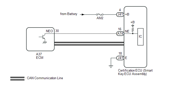
These DTCs are stored when the engine speed signal sent by the ECM via direct line and the engine speed signal sent via CAN communication do not match.
| DTC No. | Detection Item | DTC Detection Condition | Trouble Area | Note |
|---|---|---|---|---|
| B2286 | Runnable Signal Malfunction | The engine speed signal sent by the ECM via direct line and the engine speed signal sent via CAN communication do not match. (1-trip detection logic*) |
|
|
| P0335 | Crankshaft Position Sensor Circuit Malfunction (NE Signal) | The engine speed signal sent by the ECM via direct line and the engine speed signal sent via CAN communication do not match. (1-trip detection logic*) |
|
|
- *: Only detected while a malfunction is present and the engine switch is on (IG).
| Vehicle Condition when Malfunction Detected | Fail-safe Function when Malfunction Detected |
|---|---|
|
|
| DTC No. | Data List and Active Test |
|---|---|
| B2286 P0335 | Power Source Control
Starting Control
|
WIRING DIAGRAM
CAUTION / NOTICE / HINT
NOTICE:
- When using the Techstream with the engine switch off, connect the Techstream to the DLC3 and turn a courtesy light switch on and off at intervals of 1.5 seconds or less until communication between the Techstream and the vehicle begins. Then select the vehicle type under manual mode and enter the following menus: Body Electrical / Smart Access. While using the Techstream, periodically turn a courtesy light switch on and off at intervals of 1.5 seconds or less to maintain communication between the Techstream and the vehicle.
-
The smart access system with push-button start (for Start Function) uses the LIN communication system and CAN communication system. Inspect the communication function by following How to Proceed with Troubleshooting. Troubleshoot the smart access system with push-button start (for Start Function) after confirming that the communication systems are functioning properly.
Click here
.gif)
- Inspect the fuses of circuits related to this system before performing the following procedure.
-
Before replacing the certification ECU (smart key ECU assembly), refer to the smart access system with push-button start (for Start Function) Precaution.
Click here
- After repair, confirm that no DTCs are output by performing "DTC Output Confirmation Operation".
HINT:
When the cable is disconnected and reconnected to the negative (-) battery terminal, the power source mode returns to the state it was in before the cable was disconnected.
PROCEDURE
| 1. | READ VALUE USING TECHSTREAM (ENGINE CONDITION / ENGINE SPEED) |
(a) Connect the Techstream to the DLC3.
(b) Turn the Engine switch on (IG).
(c) Turn the Techstream on.
(d) Enter the following menus: Body Electrical / Power Source Control or Starting Control / Data List.
(e) Read the Data List according to the display on the Techstream.
Body Electrical > Power Source Control > Data List| Tester Display | Measurement Item | Range | Normal Condition | Diagnostic Note |
|---|---|---|---|---|
| Engine Condition | Engine state | Stop or Run | Stop: Engine stopped Run: Engine running | - |
| Tester Display |
|---|
| Engine Condition |
| Tester Display | Measurement Item | Range | Normal Condition | Diagnostic Note |
|---|---|---|---|---|
| Engine Speed | Engine speed | 0 to 16383 rpm | Fluctuates in accordance with actual engine speed | - |
| Tester Display |
|---|
| Engine Speed |
OK:
The Techstream display changes correctly in response to the engine condition.
| OK | .gif) | GO TO SFI SYSTEM (HOW TO PROCEED WITH TROUBLESHOOTING) |
|
.gif)
| 2. | CHECK HARNESS AND CONNECTOR (POWER SOURCE) |
Click here
| NG | | REPAIR OR REPLACE HARNESS OR CONNECTOR IN CIRCUIT CONNECTED TO POWER SOURCE |
|
| 3. | CHECK HARNESS AND CONNECTOR (GROUND) |
Click here
| NG | | REPAIR OR REPLACE HARNESS OR CONNECTOR |
|
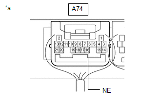
| 4. | CHECK HARNESS AND CONNECTOR (CERTIFICATION ECU (SMART KEY ECU ASSEMBLY) - ECM) |
(a) Disconnect the A74 certification ECU (smart key ECU assembly) connector.
(b) Disconnect theA37 ECM connector.
(c) Measure the resistance according to the value(s) in the table below.
Standard Resistance:
| Tester Connection | Condition | Specified Condition |
|---|---|---|
| A74-16 (NE) - A37-30 (NEO) | Always | Below 1 Ω |
| A74-16 (NE) or A37-30 (NEO) - Body ground | Always | 10 kΩ or higher |
| NG | | REPAIR OR REPLACE HARNESS OR CONNECTOR |
|
| 5. | CHECK CERTIFICATION ECU (SMART KEY ECU ASSEMBLY) |
(a) Reconnect the A74 and J41 certification ECU (smart key ECU assembly) connectors.
(b) Reconnect the A37 ECM connector.
| (c) Using an oscilloscope, check the engine speed input signal waveform at the terminal of the certification ECU (smart key ECU assembly). Standard Frequency:
|
|
| OK | | REPLACE CERTIFICATION ECU (SMART KEY ECU ASSEMBLY) |
| NG | | GO TO SFI SYSTEM (HOW TO PROCEED WITH TROUBLESHOOTING) |
 Steering Lock Position Signal Circuit Malfunction (B2285)
DESCRIPTION This DTC is stored when the steering lock position signal sent by the steering lock ECU (steering lock actuator or upper bracket assembly) via direct line and the steering lock position si ...
 System Voltage or GND Energization Malfunction (B228B)
SYSTEM DESCRIPTION This DTC is stored when there is a malfunction in the certification ECU (smart key ECU assembly) battery power supply circuit or ground circuit. DTC No. Detection Item DTC De ...
Other materials:
Lexus RX (RX 350L, RX450h) 2016-2026 Repair Manual > Sfi System: Knock Sensor 1 Bank 1 or Single Sensor Circuit Short to Ground (P032511,P033011)
DESCRIPTION A flat-type knock control sensor (non-resonant type) has a structure that can detect vibrations between approximately 5 kHz and 15 kHz. The knock control sensor is fitted onto the engine block to detect engine knocking. The knock control sensor contains a piezoelectric element which gene ...
Lexus RX (RX 350L, RX450h) 2016-2026 Repair Manual > Charging System: On-vehicle Inspection
ON-VEHICLE INSPECTION PROCEDURE 1. CHECK BATTERY CONDITION NOTICE: If the battery is weak or if the engine is difficult to start, recharge the battery and perform inspections again before returning the vehicle to the customer. (a) Check the battery for damage or deformation. If severe damage, deform ...
Lexus RX (RX 350L, RX450h) 2016-{YEAR} Owners Manual
- For your information
- Pictorial index
- For safety and security
- Instrument cluster
- Operation of each component
- Driving
- Lexus Display Audio system
- Interior features
- Maintenance and care
- When trouble arises
- Vehicle specifications
- For owners
Lexus RX (RX 350L, RX450h) 2016-{YEAR} Repair Manual

0.0091