Lexus RX (RX 350L, RX450h) 2016-2026 Repair Manual: Taillight Relay Circuit
DESCRIPTION
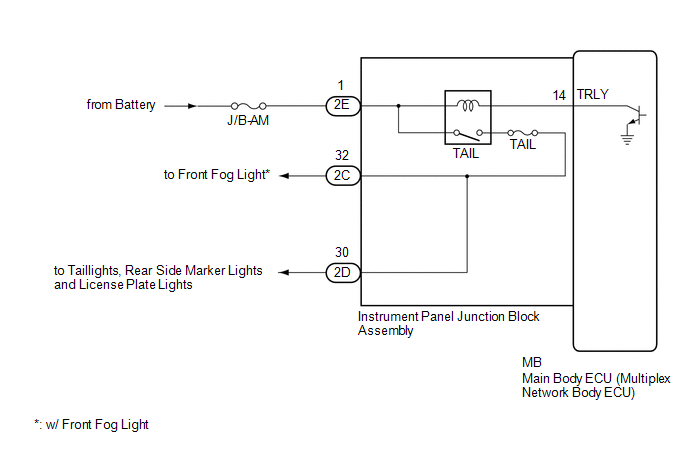
The main body ECU (multiplex network body ECU) controls the operation of the TAIL relay.
WIRING DIAGRAM
CAUTION / NOTICE / HINT
NOTICE:
- Inspect the fuses for circuits related to this system before performing the following procedure.
-
Before replacing the main body ECU (multiplex network body ECU), refer to Registration.
Click here
.gif)
PROCEDURE
| 1. | PERFORM ACTIVE TEST USING TECHSTREAM |
(a) Connect the Techstream to the DLC3.
(b) Turn the engine switch on (IG).
(c) Turn the Techstream on.
(d) Enter the following menus: Body Electrical / Main Body / Active Test.
(e) Perform the Active Test according to the display on the Techstream.
Body Electrical > Main Body > Active Test| Tester Display | Measurement Item | Control Range | Diagnostic Note |
|---|---|---|---|
| Taillight Relay | Taillight relay | OFF or ON | - |
| Tester Display |
|---|
| Taillight Relay |
OK:
Taillights illuminate.
| OK | .gif) | PROCEED TO NEXT SUSPECTED AREA SHOWN IN PROBLEM SYMPTOMS TABLE |
|
.gif)
| 2. | CHECK HARNESS AND CONNECTOR (POWER SOURCE - INSTRUMENT PANEL JUNCTION BLOCK ASSEMBLY) |
(a) Disconnect the 2E instrument panel junction block assembly connector.
(b) Measure the voltage according to the value(s) in the table below.
Standard Voltage:
| Tester Connection | Condition | Specified Condition |
|---|---|---|
| 2E-1 - Body ground | Always | 11 to 14 V |
| NG | | REPAIR OR REPLACE HARNESS OR CONNECTOR |
|
| 3. | INSPECT INSTRUMENT PANEL JUNCTION BLOCK ASSEMBLY |
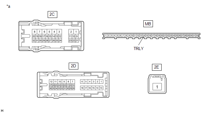
| *a | Component without harness connected (Instrument Panel Junction Block Assembly) | - | - |
(a) Remove the main body ECU (multiplex network body ECU) from the instrument panel junction block assembly.
Click here
(b) Connect a positive (+) lead from the battery to terminal 2E-1.
(c) Connect a negative (-) lead from the battery to terminal MB-14 (TRLY).
(d) Measure the voltage according to the value(s) in the table below.
Standard Voltage:
| Tester Connection | Condition | Specified Condition |
|---|---|---|
| 2C-32 - Battery negative (-) terminal | Always | 11 to 14 V |
| 2D-30 - Battery negative (-) terminal | Always | 11 to 14 V |
| OK | | REPLACE MAIN BODY ECU (MULTIPLEX NETWORK BODY ECU) |
| NG | | REPLACE INSTRUMENT PANEL JUNCTION BLOCK ASSEMBLY |
 Front Side Marker Light Circuit
DESCRIPTION When the light control switch is in the tail or head position, the main body ECU (multiplex network body ECU) sends an illumination request signal to the No. 1 headlight ECU sub-assembly t ...
 Cornering Light Circuit
DESCRIPTION The No. 1 headlight ECU sub-assembly controls the cornering lights. WIRING DIAGRAM for Multiple Beam Headlight for Single Beam Headlight CAUTION / NOTICE / HINT NOTICE:
If the No. 1 h ...
Other materials:
Lexus RX (RX 350L, RX450h) 2016-2026 Repair Manual > Power Back Door Warning Buzzer: Components
COMPONENTS ILLUSTRATION *A w/o Rear No. 2 Seat *B w/ Rear No. 2 Seat *1 BACK DOOR LOCK COVER *2 BACK DOOR TRIM BASE *3 BACK DOOR TRIM COVER LH *4 BACK DOOR TRIM COVER RH *5 BACK DOOR TRIM PANEL ASSEMBLY *6 BACK WINDOW UPPER PANEL TRIM *7 DOOR PULL HANDLE ...
Lexus RX (RX 350L, RX450h) 2016-2026 Repair Manual > Smart Access System With Push-button Start (for Entry Function): Open in Rear Floor Electrical Key Oscillator Circuit (B27A6)
DESCRIPTION The certification ECU (smart key ECU assembly) generates a request signal and transmits the signal to the No. 2 indoor electrical key antenna assembly (rear floor). For the No. 2 indoor electrical key antenna assembly (rear floor) to detect when the electrical key transmitter sub-assembl ...
Lexus RX (RX 350L, RX450h) 2016-{YEAR} Owners Manual
- For your information
- Pictorial index
- For safety and security
- Instrument cluster
- Operation of each component
- Driving
- Lexus Display Audio system
- Interior features
- Maintenance and care
- When trouble arises
- Vehicle specifications
- For owners
Lexus RX (RX 350L, RX450h) 2016-{YEAR} Repair Manual

0.0126