Lexus RX (RX 350L, RX450h) 2016-2026 Repair Manual: Front Side Marker Light Circuit
DESCRIPTION
When the light control switch is in the tail or head position, the main body ECU (multiplex network body ECU) sends an illumination request signal to the No. 1 headlight ECU sub-assembly to illuminate the front side marker lights.
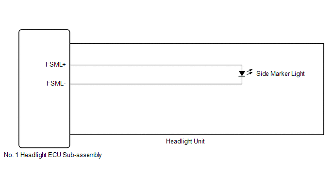
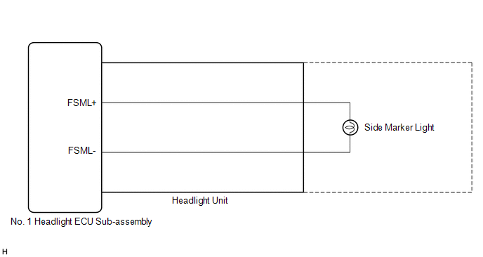
WIRING DIAGRAM
for Multiple Beam Headlight
for Single Beam Headlight
CAUTION / NOTICE / HINT
NOTICE:
-
If the No. 1 headlight ECU sub-assembly LH has been replaced, it is necessary to synchronize the vehicle information and initialize the No. 1 headlight ECU sub-assembly LH.
Click here
.gif)
-
If the headlight assembly LH has been replaced, it is necessary to synchronize the vehicle information and initialize the No. 1 headlight ECU sub-assembly LH.*1
Click here
- When replacing the No. 1 headlight ECU sub-assembly LH, always replace it with a new one. If a No. 1 headlight ECU sub-assembly LH which was installed to another vehicle is used, the information stored in it will not match the information from the vehicle and a DTC may be stored.
- When replacing the headlight assembly LH, always replace it with a new one. If a headlight assembly LH which was installed to another vehicle is used, the information stored in it will not match the information from the vehicle and a DTC may be stored.*1
-
Inspect the front side marker light bulb before performing the following procedure.*2
- *1: for TMMC Made
- *2: for Single Beam Headlight
PROCEDURE
| 1. | CONFIRM MODEL |
(a) Choose the model to be inspected.
| Result | Proceed to |
|---|---|
| for Multiple Beam Headlight | A |
| for Single Beam Headlight | B |
| B | .gif) | GO TO STEP 3 |
|
.gif)
| 2. | PERFORM ACTIVE TEST USING TECHSTREAM |
(a) Connect the Techstream to the DLC3.
(b) Turn the engine switch on (IG).
(c) Turn the Techstream on.
(d) Enter the following menus: Body Electrical / AFS / Active Test.
(e) Perform the Active Test according to the display on the Techstream.
Body Electrical > AFS > Active Test| Tester Display | Measurement Item | Control Range | Diagnostic Note |
|---|---|---|---|
| Clearance Light | Parking lights | OFF or ON | - |
| Tester Display |
|---|
| Clearance Light |
OK:
Front side marker light illuminate.
| Result | Proceed to |
|---|---|
| OK | A |
| NG (LH side front side marker light does not illuminate) | B |
| NG (RH side front side marker light does not illuminate) | C |
| A | | PROCEED TO NEXT SUSPECTED AREA SHOWN IN PROBLEM SYMPTOMS TABLE |
| B | | GO TO STEP 4 |
| C | | GO TO STEP 6 |
| 3. | PERFORM ACTIVE TEST USING TECHSTREAM |
(a) Connect the Techstream to the DLC3.
(b) Turn the engine switch on (IG).
(c) Turn the Techstream on.
(d) Enter the following menus: Body Electrical / HL AutoLeveling / Active Test.
(e) Perform the Active Test according to the display on the Techstream.
Body Electrical > HL AutoLeveling > Active Test| Tester Display | Measurement Item | Control Range | Diagnostic Note |
|---|---|---|---|
| Clearance Light | Parking lights | OFF or ON | - |
| Tester Display |
|---|
| Clearance Light |
OK:
Front side marker light illuminate.
| Result | Proceed to |
|---|---|
| OK | A |
| NG (LH side front side marker light does not illuminate) | B |
| NG (RH side front side marker light does not illuminate) | C |
| A | | PROCEED TO NEXT SUSPECTED AREA SHOWN IN PROBLEM SYMPTOMS TABLE |
| C | | GO TO STEP 6 |
|
| 4. | CHECK HEADLIGHT UNIT LH |
(a) Interchange the headlight unit LH with RH and connect the connectors.
Click here
|
| 5. | CHECK OPERATION (FRONT SIDE MARKER LIGHT) |
(a) Check that the front side marker light operates normally.
OK:
Front side marker light operates normally.
| Result | Proceed to |
|---|---|
| OK | A |
| NG (for TMC Made) | B |
| NG (for TMMC Made) | C |
| A | | REPLACE NO. 1 HEADLIGHT ECU SUB-ASSEMBLY LH |
| B | | REPLACE HEADLIGHT UNIT LH |
| C | | REPLACE HEADLIGHT ASSEMBLY LH |
| 6. | CHECK HEADLIGHT UNIT RH |
(a) Interchange the headlight unit RH with LH and connect the connectors.
Click here
|
| 7. | CHECK OPERATION (FRONT SIDE MARKER LIGHT) |
(a) Check that the front side marker light operates normally.
OK:
Front side marker light operates normally.
| Result | Proceed to |
|---|---|
| OK | A |
| NG (for TMC Made) | B |
| NG (for TMMC Made) | C |
| A | | REPLACE NO. 1 HEADLIGHT ECU SUB-ASSEMBLY RH |
| B | | REPLACE HEADLIGHT UNIT RH |
| C | | REPLACE HEADLIGHT ASSEMBLY RH |
 Outside Handle Foot Light Circuit
DESCRIPTION The main body ECU (multiplex network body ECU) controls the outside handle foot lights. WIRING DIAGRAM CAUTION / NOTICE / HINT NOTICE: Before replacing the main body ECU (multiplex networ ...
 Taillight Relay Circuit
DESCRIPTION The main body ECU (multiplex network body ECU) controls the operation of the TAIL relay. WIRING DIAGRAM CAUTION / NOTICE / HINT NOTICE:
Inspect the fuses for circuits related to this s ...
Other materials:
Lexus RX (RX 350L, RX450h) 2016-2026 Repair Manual > Rear No. 1 Seat Outer Belt Assembly: Inspection
INSPECTION PROCEDURE 1. INSPECT REAR NO. 1 SEAT OUTER BELT ASSEMBLY (a) Before installing the rear No. 1 seat outer belt assembly, check the ELR function. NOTICE: Do not disassemble the retractor. (1) When the inclination of the retractor is less than 15°, check that the belt can be pulled from ...
Lexus RX (RX 350L, RX450h) 2016-2026 Repair Manual > Audio And Visual System (for 8 Inch Display): XM Tuner Antenna Disconnected (B15FE,B15FF)
DESCRIPTION These DTCs are stored when a malfunction occurs in the telephone antenna assembly which is connected to the radio receiver assembly. DTC No. Detection Item DTC Detection Condition Trouble Area B15FE XM Tuner Antenna Disconnected The telephone antenna assembly is not conn ...
Lexus RX (RX 350L, RX450h) 2016-{YEAR} Owners Manual
- For your information
- Pictorial index
- For safety and security
- Instrument cluster
- Operation of each component
- Driving
- Lexus Display Audio system
- Interior features
- Maintenance and care
- When trouble arises
- Vehicle specifications
- For owners
Lexus RX (RX 350L, RX450h) 2016-{YEAR} Repair Manual

0.0107