Lexus RX (RX 350L, RX450h) 2016-2026 Repair Manual: Power Source Mode does not Change to ON (IG)
DESCRIPTION
If the engine switch is pressed with the electrical key transmitter sub-assembly in the cabin, the certification ECU (smart key ECU assembly) receives a signal and changes the power source mode.
Related Data List and Active Test Items| Problem Symptom | Data List and Active Test |
|---|---|
| Power source mode does not change to on (IG) but does change to on (ACC) | Power Source Control
Starting Control
|
WIRING DIAGRAM
Click here .gif)
CAUTION / NOTICE / HINT
NOTICE:
- When using the Techstream with the engine switch off, connect the Techstream to the DLC3 and turn a courtesy light switch on and off at intervals of 1.5 seconds or less until communication between the Techstream and the vehicle begins. Then select the vehicle type under manual mode and enter the following menus: Body Electrical / Smart Access. While using the Techstream, periodically turn a courtesy light switch on and off at intervals of 1.5 seconds or less to maintain communication between the Techstream and the vehicle.
-
The smart access system with push-button start (for Start Function) uses the LIN communication system and CAN communication system. Inspect the communication function by following How to Proceed with Troubleshooting. Troubleshoot the smart access system with push-button start (for Start Function) after confirming that the communication systems are functioning properly.
Click here
- Make sure that no DTCs are output. If any DTCs are output, proceed to Diagnostic Trouble Code Chart.
-
If the smart access system with push-button start (for Start Function) has been canceled, enable the system before performing troubleshooting.
Click here
- Inspect the fuses of circuits related to this system before performing the following procedure.
-
Before replacing the certification ECU (smart key ECU assembly), refer to smart access system with push-button start (for Start Function) Precaution.
Click here
- After completing repairs, confirm that the problem does not recur.
HINT:
When the cable is disconnected and reconnected to the negative (-) battery terminal, the power source mode returns to the state it was in before the cable was disconnected.
PROCEDURE
| 1. | CHECK FOR DTC |
(a) Using the Techstream, check for certification ECU (smart key ECU assembly) DTCs.
Body Electrical > Power Source Control > Trouble Codes Body Electrical > Smart Access > Trouble Codes Body Electrical > Starting Control > Trouble Codes| Result | Proceed to |
|---|---|
| DTCs are not output | A |
| Smart access system with push-button start (for Start Function) DTCs are output | B |
| B | .gif) | GO TO DIAGNOSTIC TROUBLE CODE CHART |
|
.gif)
| 2. | CHECK HARNESS AND CONNECTOR (CERTIFICATION ECU (SMART KEY ECU ASSEMBLY) - INSTRUMENT PANEL JUNCTION BLOCK ASSEMBLY) |
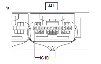
(a) Disconnect the J41 certification ECU (smart key ECU assembly) connector.
(b) Disconnect the 2A and 2B instrument panel junction block assembly connectors.
(c) Measure the resistance according to the value(s) in the table below.
Standard Resistance:
| Tester Connection | Condition | Specified Condition |
|---|---|---|
| J41-17 (IG1D) - 2A-17 | Always | Below 1 Ω |
| 2B-3 - Body ground | Always | Below 1 Ω |
| J41-17 (IG1D) or 2A-17 - Body ground | Always | 10 kΩ or higher |
| NG | | REPAIR OR REPLACE HARNESS OR CONNECTOR |
|
| 3. | CHECK HARNESS AND CONNECTOR (INSTRUMENT PANEL JUNCTION BLOCK ASSEMBLY - SEMICONDUCTOR PWR INTEGRATION ECU) |
(a) Disconnect the 1E semiconductor pwr integration ECU connector.
(b) Disconnect the 2C instrument panel junction block assembly connector.
(c) Measure the resistance according to the value(s) in the table below.
Standard Resistance:
| Tester Connection | Condition | Specified Condition |
|---|---|---|
| 2C-12 - 1E-1 | Always | Below 1 Ω |
| 2C-12 or 1E-1 - Body ground | Always | 10 kΩ or higher |
| NG | | REPAIR OR REPLACE HARNESS OR CONNECTOR |
|
| 4. | CHECK HARNESS AND CONNECTOR (INSTRUMENT PANEL JUNCTION BLOCK ASSEMBLY - IG1-MAIN RELAY) |
(a) Remove the IG1-MAIN relay.
(b) Measure the resistance according to the value(s) in the table below.
Standard Resistance:
| Tester Connection | Condition | Specified Condition |
|---|---|---|
| 2C-12 - 1 (IG1-MAIN relay) | Always | Below 1 Ω |
| 2 (IG1-MAIN relay) - Body ground | Always | Below 1 Ω |
| 2C-12 or 1 (IG1-MAIN relay) - Body ground | Always | 10 kΩ or higher |
| NG | | REPAIR OR REPLACE HARNESS OR CONNECTOR |
|
| 5. | CHECK INSTRUMENT PANEL JUNCTION BLOCK ASSEMBLY (IG1 NO. 1, IG1 NO. 2 RELAY) |
(a) Remove the instrument panel junction block assembly.
Click here
(b) Measure the resistance according to the value(s) in the table below.
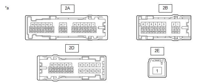
| *a | Component without harness connected (Instrument Panel Junction Block Assembly) | - | - |
Standard Resistance:
| Tester Connection | Condition | Specified Condition |
|---|---|---|
| 2A-17 - 2B-3 | 20°C (68°F) | 130.92 to 190.69 Ω |
| 2E-1 - 2A-35 | Battery voltage applied between terminals 2A-17 and 2B-3 | Below 1 Ω |
| Battery voltage not applied between terminals 2A-17 and 2B-3 | 10 kΩ or higher | |
| 2E-1 - 2D-12 | Battery voltage applied between terminals 2A-17 and 2B-3 | Below 1 Ω |
| Battery voltage not applied between terminals 2A-17 and 2B-3 | 10 kΩ or higher |
| NG | | REPLACE INSTRUMENT PANEL JUNCTION BLOCK ASSEMBLY |
|
| 6. | INSPECT SEMICONDUCTOR POWER INTEGRATION ECU (IG2 RELAY) |
(a) Remove the semiconductor pwr integration ECU.
Click here
(b) Inspect the semiconductor pwr integration ECU.
Click here
| NG | | REPLACE SEMICONDUCTOR POWER INTEGRATION ECU (IG2 RELAY) |
|
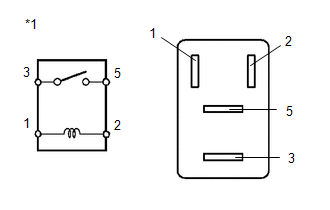
| 7. | INSPECT IG1-MAIN RELAY |
(a) Remove the IG1-MAIN relay.
| (b) Measure the resistance according to the value(s) in the table below. Standard Resistance:
|
|
| NG | | REPLACE IG1-MAIN RELAY |
|
| 8. | CHECK CERTIFICATION ECU (SMART KEY ECU ASSEMBLY) |
(a) Reconnect the J41 certification ECU (smart key ECU assembly) connector.
(b) Install the instrument panel junction block assembly.
Click here
(c) Install the semiconductor pwr integration ECU.
Click here
(d) Install the IG1-MAIN relay.
| (e) Measure the voltage according to the value(s) in the table below. Standard Voltage:
|
|
| OK | | USE SIMULATION METHOD TO CHECK |
| NG | | REPLACE CERTIFICATION ECU (SMART KEY ECU ASSEMBLY) |
 Power Source Mode does not Change to ON (IG and ACC)
DESCRIPTION If any of the following operations are performed, the certification ECU (smart key ECU assembly) receives a signal, and changes the power source mode.
With the electrical key transmitte ...
 Power Source Mode does not Change to ON (ACC)
DESCRIPTION If the engine switch is pressed with the electrical key transmitter sub-assembly in the cabin, the certification ECU (smart key ECU assembly) receives a signal and changes the power source ...
Other materials:
Lexus RX (RX 350L, RX450h) 2016-2026 Repair Manual > Lumbar Switch: Components
COMPONENTS ILLUSTRATION *A for Sports Seat Type - - *1 FRONT SEAT CUSHION SHIELD *2 INNER NO. 1 FRONT SEAT CUSHION SHIELD ILLUSTRATION *A w/ Seat Position Memory System - - *1 FRONT LUMBAR POWER SEAT SWITCH *2 FRONT SEAT CUSHION SHIELD *3 POSITION CON ...
Lexus RX (RX 350L, RX450h) 2016-2026 Repair Manual > Panoramic View Monitor System: Problem Symptoms Table
PROBLEM SYMPTOMS TABLE NOTICE:
The following inspection procedure of the panoramic view monitor system is described on the assumption that the navigation system*1 or audio and visual system*2 is normal. If the navigation system has any malfunction, first proceed with troubleshooting of the naviga ...
Lexus RX (RX 350L, RX450h) 2016-{YEAR} Owners Manual
- For your information
- Pictorial index
- For safety and security
- Instrument cluster
- Operation of each component
- Driving
- Lexus Display Audio system
- Interior features
- Maintenance and care
- When trouble arises
- Vehicle specifications
- For owners
Lexus RX (RX 350L, RX450h) 2016-{YEAR} Repair Manual

0.0203