
Lexus RX (RX 350L, RX450h) 2016-2026 Repair Manual: Parts Location
PARTS LOCATION
ILLUSTRATION
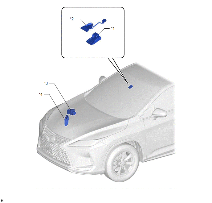
| *1 | FORWARD RECOGNITION CAMERA | *2 | FORWARD RECOGNITION WITH HEATER HOOD SUB-ASSEMBLY |
| *3 | SKID CONTROL ECU (BRAKE ACTUATOR ASSEMBLY) | *4 | ECM |
ILLUSTRATION
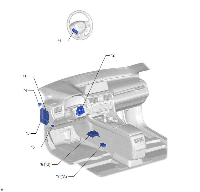
| *A | for TFT Meter Type | *B | for Optitron Meter Type |
| *1 | STEERING VIBRATION ECU | *2 | SPIRAL CABLE WITH SENSOR SUB-ASSEMBLY - SPIRAL CABLE SUB-ASSEMBLY - STEERING SENSOR |
| *3 | MAIN BODY ECU (MULTIPLEX NETWORK BODY ECU) | *4 | SKID CONTROL BUZZER ASSEMBLY |
| *5 | INSTRUMENT PANEL JUNCTION BLOCK ASSEMBLY - ECU-IG1 NO. 2 FUSE | *6 | AIRBAG SENSOR ASSEMBLY |
| *7 | YAW RATE SENSOR ASSEMBLY | *8 | DLC3 |
 System Diagram
SYSTEM DIAGRAM ...
 How To Proceed With Troubleshooting
CAUTION / NOTICE / HINT HINT:
Before performing troubleshooting for the front camera system, perform troubleshooting for the pre-collision system.
Click here
If a pre-collision system related w ...
Other materials:
Lexus RX (RX 350L, RX450h) 2016-2026 Repair Manual > Seat Memory Switch: Removal
REMOVAL PROCEDURE 1. REMOVE FRONT DOOR INSIDE HANDLE BEZEL PLUG LH Click here 2. REMOVE MULTIPLEX NETWORK MASTER SWITCH ASSEMBLY WITH FRONT DOOR UPPER ARMREST BASE PANEL Click here 3. REMOVE DOOR ARMREST COVER LH Click here 4. REMOVE COURTESY LIGHT ASSEMBLY Click here 5. REMOVE FRON ...
Lexus RX (RX 350L, RX450h) 2016-2026 Repair Manual > Audio And Visual System (for 12.3 Inch Display): Panel Switches do not Function
CAUTION / NOTICE / HINT NOTICE: Depending on the parts that are replaced during vehicle inspection or maintenance, performing initialization, registration or calibration may be needed. Refer to Precaution for Audio and Visual System. Click here PROCEDURE 1. CHECK PANEL SWITCH (a) Check fo ...
Lexus RX (RX 350L, RX450h) 2016-{YEAR} Owners Manual
- For your information
- Pictorial index
- For safety and security
- Instrument cluster
- Operation of each component
- Driving
- Lexus Display Audio system
- Interior features
- Maintenance and care
- When trouble arises
- Vehicle specifications
- For owners
Lexus RX (RX 350L, RX450h) 2016-{YEAR} Repair Manual

0.011