Lexus RX (RX 350L, RX450h) 2016-2026 Repair Manual: Terminals Of Ecu
TERMINALS OF ECU
CHECK MAIN BODY ECU (MULTIPLEX NETWORK BODY ECU) AND INSTRUMENT PANEL JUNCTION BLOCK ASSEMBLY
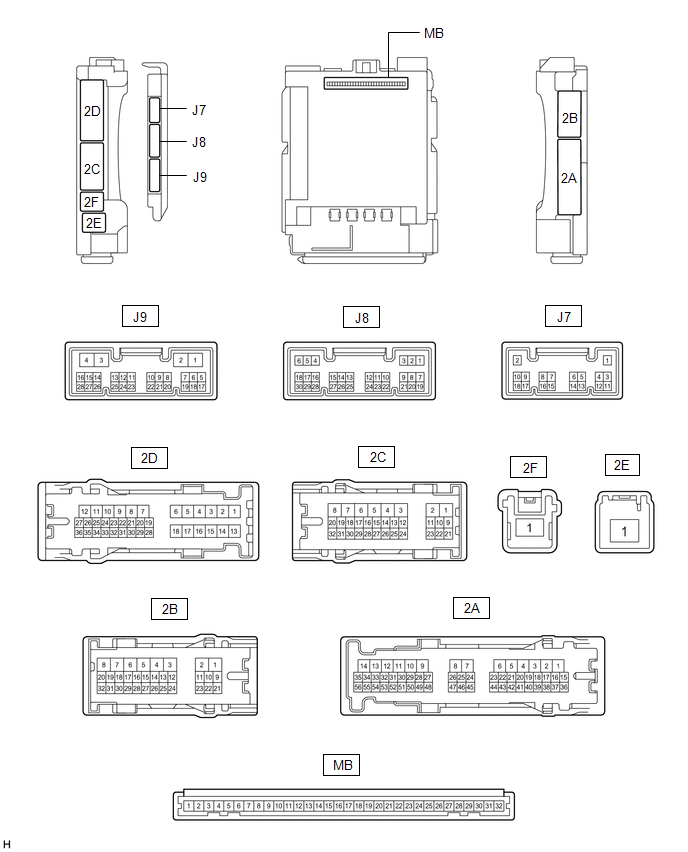
(a) Remove the main body ECU (multiplex network body ECU) from the instrument panel junction block assembly.
Click here .gif)
(b) Reconnect the instrument panel junction block assembly connectors.
(c) Measure the resistance and voltage according to the value(s) in the table below.
HINT:
Measure the values on the wire harness side with the connector disconnected.
| Terminal No. (Symbol) | Wiring Color | Terminal Description | Condition | Specified Condition |
|---|---|---|---|---|
| MB-31 (BECU) - Body ground | - | Battery power supply | Always | 11 to 14 V |
| MB-32 (IG) - Body ground | - | Ignition power supply (IG signal) | Engine switch off | Below 1 V |
| Engine switch on (IG) | 11 to 14 V | |||
| MB-30 (ACC) - Body ground | - | Ignition power supply (ACC signal) | Engine switch off | Below 1 V |
| Engine switch on (ACC) | 11 to 14 V | |||
| MB-11 (GND1) - Body ground | - | Ground | Always | Below 1 Ω |
| J8-6 (FLCY) - Body ground | P - Body ground | Front door courtesy light switch assembly (for LH) input | Front door LH closed | 10 kΩ or higher |
| Front door LH open | Below 1 Ω | |||
| J8-27 (FRCY) - Body ground | R - Body ground | Front door courtesy light switch assembly (for RH) input | Front door RH closed | 10 kΩ or higher |
| Front door RH open | Below 1 Ω | |||
| MB-13 (LCTY) - Body ground | - | Rear door courtesy light switch assembly (for LH) input | Rear door LH closed | 10 kΩ or higher |
| Rear door LH open | Below 1 Ω | |||
| MB-2 (RCTY) - Body ground | - | Rear door courtesy light switch assembly (for RH) input | Rear door RH closed | 10 kΩ or higher |
| Rear door RH open | Below 1 Ω | |||
| J8-11 (HCTY) - Body ground | R - Body ground | Engine hood courtesy switch input | Engine hood open | 10 kΩ or higher |
| Engine hood closed | Below 1 Ω | |||
| MB-14 (TRLY) - Body ground | - | Taillight relay drive output | Always | 11 to 14 V |
(d) Install the main body ECU (multiplex network body ECU) to instrument panel junction block assembly.
Click here
(e) Measure the voltage and check for pulses according to the value(s) in the table below.
| Terminal No. (Symbol) | Wiring Color | Terminal Description | Condition | Specified Condition |
|---|---|---|---|---|
| 2B-13 (LSFL) - Body ground | B - Body ground | Front door LH unlock detection switch input | Front door LH unlocked | Below 1 V |
| Front door LH locked | Pulse generation | |||
| 2B-12 (LSFR) - Body ground | P - Body ground | Front door RH unlock detection switch input | Front door RH unlocked | Below 1 V |
| Front door RH locked | Pulse generation | |||
| J8-29 (L2) - Body ground | P - Body ground | Driver door key-linked lock input | Driver door key cylinder turned to lock position | Below 1 V |
| Driver door key cylinder off | Pulse generation | |||
| J8-2 (UL3) - Body ground | V - Body ground | Driver door key-linked unlock input | Driver door key cylinder turned to unlock position | Below 1 V |
| Driver door key cylinder off | Pulse generation | |||
| 2B-14 (LSWL) - Body ground | V - Body ground | Rear door LH unlock detection switch input | Rear door LH unlocked | Below 1 V |
| Rear door LH locked | Pulse generation | |||
| J9-2 (LSWR) - Body ground | L - Body ground | Rear door RH unlock detection switch input | Rear door RH unlocked | Below 1 V |
| Rear door RH locked | Pulse generation | |||
| 2C-26 (SH) - Body ground*1 | L - Body ground | Security horn assembly drive | Security horn assembly sounding (Theft deterrent system in alarm sounding state) | Pulse generation (Below 1 V ← → 11 to 14 V) |
| J9-18 (SSCL) - Body ground*2 | W - Body ground | Theft warning siren assembly drive | Theft warning siren assembly sounding (Theft deterrent system in alarm sounding state) | Pulse generation (Below 1 V ← → 11 to 14 V) |
| 2C-27 (HORN) - Body ground | G - Body ground | Vehicle horns drive | Vehicle horns sounding (Theft deterrent system in alarm sounding state) | Pulse generation (Below 1 V ← → 11 to 14 V) |
| 2C-31 (HRLY) - Body ground | V - Body ground*3 B - Body ground*4 | Headlight relay drive output | Low beams blinking (Theft deterrent system in alarm sounding state) | Pulse generation (Below 1 V ← → 11 to 14 V) |
| 2B-29 (ILE) - Body ground | GR - Body ground | Interior lights drive output | Interior lights illuminated (Theft deterrent system in alarm sounding state) | Below 1 V |
- *1: w/ Security Horn Assembly
- *2: w/o Security Horn Assembly
- *3: w/ Automatic Headlight Beam Level Control System
- *4: w/o Automatic Headlight Beam Level Control System
 Problem Symptoms Table
PROBLEM SYMPTOMS TABLE NOTICE: Before replacing the main body ECU (multiplex network body ECU), refer to Registration. Click here HINT:
Troubleshooting of the theft deterrent system is based on ...
 Data List / Active Test
DATA LIST / ACTIVE TEST DATA LIST HINT: Using the Techstream to read the Data List allows the values or states of switches, sensors, actuators and other items to be read without removing any parts. Th ...
Other materials:
Lexus RX (RX 350L, RX450h) 2016-2026 Repair Manual > Audio And Visual System (for 8 Inch Display): Microphone Circuit
DESCRIPTION
The radio receiver assembly and telephone microphone assembly are connected to each other using the microphone connection detection signal lines.
Using this circuit, the radio receiver assembly sends power to the telephone microphone assembly, and the telephone microphone assembly s ...
Lexus RX (RX 350L, RX450h) 2016-2026 Repair Manual > Pre-collision System: Dtc Check / Clear
DTC CHECK / CLEAR CHECK DTC (a) Connect the Techstream to the DLC3. (b) Turn the engine switch on (IG). (c) Turn the Techstream on. (d) Enter the following menus: Body Electrical / Pre-Collision System / Trouble Codes. Body Electrical > Pre-Collision System > Trouble Codes (e) Check for DTCs ( ...
Lexus RX (RX 350L, RX450h) 2016-{YEAR} Owners Manual
- For your information
- Pictorial index
- For safety and security
- Instrument cluster
- Operation of each component
- Driving
- Lexus Display Audio system
- Interior features
- Maintenance and care
- When trouble arises
- Vehicle specifications
- For owners
Lexus RX (RX 350L, RX450h) 2016-{YEAR} Repair Manual

0.0094