Lexus RX (RX 350L, RX450h) 2016-2026 Repair Manual: Security Horn Circuit
DESCRIPTION
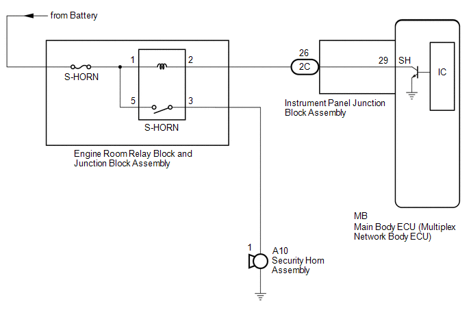
When the theft deterrent system is switched from the armed state to the alarm sounding state, the main body ECU (multiplex network body ECU) transmits a signal to cause the security horn assembly to sound at intervals of 0.4 seconds.
WIRING DIAGRAM
CAUTION / NOTICE / HINT
NOTICE:
-
Before replacing the main body ECU (multiplex network body ECU), refer to Registration.
Click here
.gif)
- Inspect the fuses for circuits related to this system before performing the following procedure.
PROCEDURE
| 1. | PERFORM ACTIVE TEST USING TECHSTREAM (SECURITY HORN) |
(a) Connect the Techstream to the DLC3.
(b) Turn the engine switch on (IG).
(c) Turn the Techstream on.
(d) Enter the following menus: Body Electrical / Main Body / Active Test.
(e) Perform the Active Test according to the display on the Techstream.
Body Electrical > Main Body > Active Test| Tester Display | Measurement Item | Control Range | Diagnostic Note |
|---|---|---|---|
| Security Horn | Security horn Assembly | OFF/ON | - |
| Tester Display |
|---|
| Security Horn |
OK:
The security horn assembly sounds and stops correctly when operated through the Techstream.
| OK | .gif) | REPLACE MAIN BODY ECU (MULTIPLEX NETWORK BODY ECU) |
|
.gif)
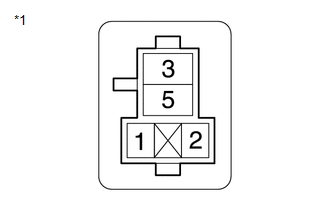
| 2. | INSPECT SECURITY HORN ASSEMBLY |
(a) Remove the security horn assembly.
Click here
(b) Inspect the security horn assembly.
Click here
| NG | | REPLACE SECURITY HORN ASSEMBLY |
|
| 3. | INSPECT S-HORN RELAY |
| (a) Remove the S-HORN relay from the engine room relay block. |
|
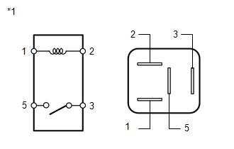
(b) Measure the resistance according to the value(s) in the table below.
Standard Resistance:
| Tester Connection | Condition | Specified Condition |
|---|---|---|
| 3 - 5 | Battery voltage not applied between terminals 1 and 2 | 10 kΩ or higher |
| 3 - 5 | Battery voltage applied between terminals 1 and 2 | Below 1 Ω |
| NG | | REPLACE S-HORN RELAY |
|
| 4. | INSPECT INSTRUMENT PANEL JUNCTION BLOCK ASSEMBLY |
(a) Remove the main body ECU (multiplex network body ECU).
Click here
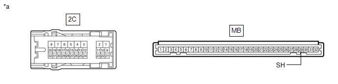
| *a | Component without harness connected (Instrument Panel Junction Block Assembly) | - | - |
(b) Disconnect the 2C instrument panel junction block assembly connector.
(c) Measure the resistance according to the value(s) in the table below.
Standard Resistance:
| Tester Connection | Condition | Specified Condition |
|---|---|---|
| 2C-26 - MB-29 (SH) | Always | Below 1 Ω |
| NG | | REPLACE INSTRUMENT PANEL JUNCTION BLOCK ASSEMBLY |
|
| 5. | CHECK HARNESS AND CONNECTOR (BATTERY - S-HORN RELAY) |
| (a) Measure the voltage according to the value(s) in the table below. Standard Voltage:
|
|
| NG | | REPAIR OR REPLACE HARNESS OR CONNECTOR |
|
| 6. | CHECK HARNESS AND CONNECTOR (S-HORN RELAY - SECURITY HORN ASSEMBLY) |
| (a) Measure the resistance according to the value(s) in the table below. Standard Resistance:
|
|
| NG | | REPAIR OR REPLACE HARNESS OR CONNECTOR |
|
| 7. | CHECK HARNESS AND CONNECTOR (S-HORN RELAY - INSTRUMENT PANEL JUNCTION BLOCK ASSEMBLY) |
| (a) Measure the resistance according to the value(s) in the table below. Standard Resistance:
|
|
| OK | | REPLACE MAIN BODY ECU (MULTIPLEX NETWORK BODY ECU) |
| NG | | REPAIR OR REPLACE HARNESS OR CONNECTOR |
 Horn Circuit
DESCRIPTION When the theft deterrent system is switched from the armed state to the alarm sounding state, the main body ECU (multiplex network body ECU) transmits a signal to cause the horns to sound ...
 Theft Warning Siren Circuit
DESCRIPTION The theft warning siren assembly sounds if either of the following conditions is met:
The theft deterrent system is in the alarm sounding state.
The theft warning siren assembly is in ...
Other materials:
Lexus RX (RX 350L, RX450h) 2016-2026 Repair Manual > Navigation System: AV Signal Stoppage (Low Battery Voltage) (B158F)
DESCRIPTION This DTC is stored when a video or audio signal is interrupted due to battery voltage input to the radio receiver assembly dropping temporarily. DTC No. Detection Item DTC Detection Condition Trouble Area B158F AV Signal Stoppage (Low Battery Voltage) A video or audio si ...
Lexus RX (RX 350L, RX450h) 2016-2026 Repair Manual > Seat Heater System: Operation Check
OPERATION CHECK CHECK FRONT SEAT HEATER (a) Turn the engine switch on (IG). (b) Turn the refreshing seat switch (for front side) (heater position) on and check that the indicator illuminates and the surface of the front seat warms up. (c) Check that the front seat surface temperature changes accordi ...
Lexus RX (RX 350L, RX450h) 2016-{YEAR} Owners Manual
- For your information
- Pictorial index
- For safety and security
- Instrument cluster
- Operation of each component
- Driving
- Lexus Display Audio system
- Interior features
- Maintenance and care
- When trouble arises
- Vehicle specifications
- For owners
Lexus RX (RX 350L, RX450h) 2016-{YEAR} Repair Manual

0.0101