Lexus RX (RX 350L, RX450h) 2016-2026 Repair Manual: Theft Warning Siren Circuit
DESCRIPTION
The theft warning siren assembly sounds if either of the following conditions is met:
- The theft deterrent system is in the alarm sounding state.
- The theft warning siren assembly is in the armed state when the power source, ground or communication line is open.
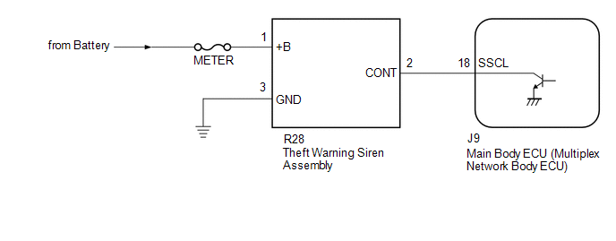
WIRING DIAGRAM
CAUTION / NOTICE / HINT
NOTICE:
-
Before replacing the main body ECU (multiplex network body ECU), refer to Registration.
Click here
.gif)
- Inspect the fuses for circuits related to this system before performing the following procedure.
PROCEDURE
| 1. | PERFORM ACTIVE TEST USING TECHSTREAM (SECURITY HORN2) |
(a) Connect the Techstream to the DLC3.
(b) Turn the engine switch on (IG).
(c) Turn the Techstream on.
(d) Enter the following menus: Body Electrical / Main Body / Active Test.
(e) Perform the Active Test according to the display on the Techstream.
Body Electrical > Main Body > Active Test| Tester Display | Measurement Item | Control Range | Diagnostic Note |
|---|---|---|---|
| Security Horn2 | Theft warning siren assembly | OFF/ON | - |
| Tester Display |
|---|
| Security Horn2 |
OK:
The theft warning siren assembly sounds and stops correctly when operated using the Techstream.
| OK | .gif) | REPLACE MAIN BODY ECU (MULTIPLEX NETWORK BODY ECU) |
|
.gif)
| 2. | CHECK HARNESS AND CONNECTOR (BATTERY - THEFT WARNING SIREN ASSEMBLY - BODY GROUND) |
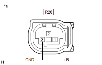
| (a) Disconnect the R28 theft warning siren assembly connector. |
|
(b) Measure the voltage and resistance according to the value(s) in the table below.
Standard Voltage:
| Tester Connection | Condition | Specified Condition |
|---|---|---|
| R28-1 (+B) - Body ground | Always | 11 to 14 V |
Standard Resistance:
| Tester Connection | Condition | Specified Condition |
|---|---|---|
| R28-3 (GND) - Body ground | Always | Below 1 Ω |
| NG | | REPAIR OR REPLACE HARNESS OR CONNECTOR |
|
| 3. | CHECK HARNESS AND CONNECTOR (MAIN BODY ECU (MULTIPLEX NETWORK BODY ECU) - THEFT WARNING SIREN ASSEMBLY) |
(a) Disconnect the J9 main body ECU (multiplex network body ECU) connector.
(b) Measure the resistance according to the value(s) in the table below.
Standard Resistance:
| Tester Connection | Condition | Specified Condition |
|---|---|---|
| J9-18 (SSCL) - R28-2 (CONT) | Always | Below 1 Ω |
| J9-18 (SSCL) or R28-2 (CONT) - Body ground | Always | 10 kΩ or higher |
| NG | | REPAIR OR REPLACE HARNESS OR CONNECTOR |
|
| 4. | REPLACE THEFT WARNING SIREN ASSEMBLY |
(a) Temporarily replace the theft warning siren assembly with a new or known good one.
Click here
|
| 5. | CHECK THEFT WARNING SIREN ASSEMBLY |
(a) Turn the engine switch on (IG), then off.
(b) Set the theft deterrent system to "ARMED STATE".
Click here
(c) Check that the security indicator changes from illuminated to blinking.
(d) Change the theft deterrent system to "ALARM SOUNDING STATE".
Click here
(e) Check that the theft warning siren assembly is sounding.
OK:
Theft warning siren assembly is sounding.
| OK | | END (THEFT WARNING SIREN ASSEMBLY WAS DEFECTIVE) |
| NG | | REPLACE MAIN BODY ECU (MULTIPLEX NETWORK BODY ECU) |
 Security Horn Circuit
DESCRIPTION When the theft deterrent system is switched from the armed state to the alarm sounding state, the main body ECU (multiplex network body ECU) transmits a signal to cause the security horn a ...
 Power Source Circuit
DESCRIPTION Based on changes in the power source voltage, the main body ECU (multiplex network body ECU) can detect if the battery has been disconnected and reconnected. WIRING DIAGRAM CAUTION / NOTI ...
Other materials:
Lexus RX (RX 350L, RX450h) 2016-2026 Repair Manual > Refrigerant (for Hfo-1234yf(r1234yf)): Replacement
REPLACEMENT PROCEDURE 1. RECOVER REFRIGERANT FROM REFRIGERATION SYSTEM (a) Start the engine. (b) Operate the compressor under the following conditions: Item Condition Operating Time 3 minutes or more Temperature setting Max cold Blower speed High Engine Idling A/C sw ...
Lexus RX (RX 350L, RX450h) 2016-2026 Repair Manual > Rear Bumper (w/ Rear No. 2 Seat): Removal
REMOVAL CAUTION / NOTICE / HINT The necessary procedures (adjustment, calibration, initialization, or registration) that must be performed after parts are removed and installed, or replaced during rear bumper assembly removal/installation are shown below. Necessary Procedures After Parts Removed/Ins ...
Lexus RX (RX 350L, RX450h) 2016-{YEAR} Owners Manual
- For your information
- Pictorial index
- For safety and security
- Instrument cluster
- Operation of each component
- Driving
- Lexus Display Audio system
- Interior features
- Maintenance and care
- When trouble arises
- Vehicle specifications
- For owners
Lexus RX (RX 350L, RX450h) 2016-{YEAR} Repair Manual

0.0102