Lexus RX (RX 350L, RX450h) 2016-2026 Repair Manual: Terminals Of Ecu
TERMINALS OF ECU
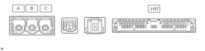
| Terminal No. (Symbol) | Wiring Color | Terminal Description | Condition | Specified Condition |
|---|---|---|---|---|
| J157-1 (+B) - J157-20 (E) | Y - W-B | Power source (+B) | Always | 11 to 14 V |
| J157-3 (SIG-) - J157-20 (E) | G - W-B | Ground | Always | Below 1 V |
| J157-4 (IND1) - J157-20 (E) | LG - W-B | Manual (SOS) switch red indicator illumination signal | For 2 seconds after turning the engine switch on (IG) | 1 to 8.5 V |
| Engine switch off | Below 1 V | |||
| J157-5 (MCVD) - J157-20 (E) | L - W-B | Telephone microphone assembly power supply | Engine switch on (ACC) | 4 to 6 V |
| Engine switch off | Below 1 V | |||
| J157-6 (MCI+) - J157-20 (E) | P - W-B | Receive microphone voice signal | Voice being input to telephone microphone assembly | A waveform synchronized with microphone voice signal is input |
| J157-7 (MCI-) - J157-20 (E) | G - W-B | Receive microphone voice signal | Always | Below 1 V |
| J157-13 (GSW) - J157-20 (E) | L - W-B | Collision detection signal | Engine switch on (IG) | Pulse generation (Refer to waveform1) |
| J157-19 (IG2) - J157-20 (E) | B - W-B | Power source (IG) | Engine switch on (IG) | 11 to 14 V |
| Engine switch off | Below 1 V | |||
| J157-20 (E) - Body ground | W-B - Body ground | Ground | Always | Below 1 Ω |
| J157-21 (SIG1) - J157-3 (SIG-) | R - G | Manual (SOS) switch button condition signal | Manual (SOS) switch not pressed | 1.3 to 1.9 V |
| Manual (SOS) switch pressed | 0.5 to 0.8 V | |||
| J157-22 (IND2) - J157-20 (E) | V - W-B | Manual (SOS) switch green indicator illumination signal | For 2 seconds after turning the engine switch on (IG) | 1 to 8.5 V |
| Engine switch off | Below 1 V | |||
| J157-23 (SGND) - J157-20 (E) | Shielded - W-B | Shield ground | Always | Below 1 Ω |
| J157-25 (CANP) | R | CAN communication signal | - | - |
| J157-26 (CANN) | W | CAN communication signal | - | - |
CHECK DCM (TELEMATICS TRANSCEIVER)
(a) Oscilloscope waveform:
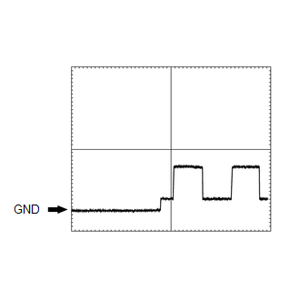
(1) Waveform 1
| Item | Condition |
|---|---|
| Tester connection | J157-13 (GSW) - J157-20 (E) |
| Tool setting | 5.0 V/DIV., 20 ms/DIV. |
| Vehicle condition | Engine switch on (IG) |
CHECK RADIO RECEIVER ASSEMBLY
w/o Navigation System: Click here .gif)
w/ Navigation System: Click here
 Diagnosis System
DIAGNOSIS SYSTEM DESCRIPTION (a) The DCM (telematics transceiver) control the vehicle safety connect system functions. Safety connect system data and Diagnostic Trouble Codes (DTCs) can be read throug ...
 Dtc Check / Clear
DTC CHECK / CLEAR CHECK DTC (a) Connect the Techstream to the DLC3. (b) Turn the engine switch on (IG). (c) Turn the Techstream on. (d) Enter the following menus: Body Electrical / Telematics / Troubl ...
Other materials:
Lexus RX (RX 350L, RX450h) 2016-2026 Repair Manual > Rear Evaporator Temperature Sensor: Inspection
INSPECTION PROCEDURE 1. INSPECT NO. 2 AIR CONDITIONING HARNESS ASSEMBLY (a) Measure the resistance according to the value(s) in the table below. *a Component without harness connected (No. 2 Air Conditioning Harness Assembly) *b Sensing Portion *c Resistance (kΩ) *d Temperature ...
Lexus RX (RX 350L, RX450h) 2016-2026 Repair Manual > Power Back Door System (w/ Outside Door Control Switch): Initialization
INITIALIZATION INITIALIZE MULTIPLEX NETWORK DOOR ECU NOTICE: Initialization of the multiplex network door ECU (back door initial position learning) is necessary if any of the following have been performed with the back door open.
The cable is disconnected from the negative (-) battery terminal.
...
Lexus RX (RX 350L, RX450h) 2016-{YEAR} Owners Manual
- For your information
- Pictorial index
- For safety and security
- Instrument cluster
- Operation of each component
- Driving
- Lexus Display Audio system
- Interior features
- Maintenance and care
- When trouble arises
- Vehicle specifications
- For owners
Lexus RX (RX 350L, RX450h) 2016-{YEAR} Repair Manual

0.0105