Lexus RX (RX 350L, RX450h) 2016-2026 Repair Manual: Microphone Circuit Open (B157213)
DESCRIPTION
This DTC is stored when the DCM (telematics transceiver) detects a malfunction in the telephone microphone assembly circuit.
| DTC No. | Detection Item | DTC Detection Condition | Trouble Area |
|---|---|---|---|
| B157213 | Microphone Circuit Open | Current at terminal MCVD is lower than the malfunction threshold for 10 seconds or more while the engine switch is on (IG) |
|
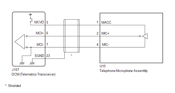
WIRING DIAGRAM
CAUTION / NOTICE / HINT
NOTICE:
Depending on the parts that are replaced during vehicle inspection or maintenance, performing initialization, registration or calibration may be needed. Refer to Precaution for Safety Connect System.
Click here .gif)
PROCEDURE
| 1. | CHECK DTC |
(a) Turn the engine switch off.
(b) Connect the Techstream to the DLC3.
(c) Turn the engine switch on (IG) and wait for 10 seconds or more.
(d) Turn the Techstream on.
(e) Clear the DTCs.
Body Electrical > Telematics > Clear DTCs(f) Check for DTCs and check that no DTCs are output.
Body Electrical > Telematics > Trouble CodesOK:
No DTCs are output.
| OK | .gif) | USE SIMULATION METHOD TO CHECK |
|
.gif)
| 2. | CHECK HARNESS AND CONNECTOR (DCM [TELEMATICS TRANSCEIVER] - TELEPHONE MICROPHONE ASSEMBLY) |
(a) Disconnect the J157 DCM (telematics transceiver) connector.
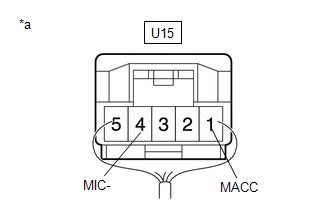
(b) Disconnect the U15 telephone microphone assembly connector.
(c) Measure the resistance according to the value(s) in the table below.
Standard Resistance:
| Tester Connection | Condition | Specified Condition |
|---|---|---|
| J157-5 (MCVD) - U15-1 (MACC) | Always | Below 1 Ω |
| J157-6 (MCI+) - U15-2 (MIC+) | Always | Below 1 Ω |
| J157-7 (MCI-) - U15-4 (MIC-) | Always | Below 1 Ω |
| J157-23 (SGND) - Body ground | Always | 10 kΩ or higher |
| J157-5 (MCVD) or U15-1 (MACC) - Body ground | Always | 10 kΩ or higher |
| J157-6 (MCI+) or U15-2 (MIC+) - Body ground | Always | 10 kΩ or higher |
| J157-7 (MCI-) or U15-4 (MIC-) - Body ground | Always | 10 kΩ or higher |
| NG | | REPAIR OR REPLACE HARNESS OR CONNECTOR |
|
| 3. | CHECK DCM (TELEMATICS TRANSCEIVER) (TELEPHONE MICROPHONE ASSEMBLY POWER SOURCE) |
| (a) Remove the telephone microphone assembly but do not disconnect the connectors. Click here |
|
(b) Measure the voltage and resistance according to the value(s) in the table below.
Standard Voltage:
| Tester Connection | Switch Condition | Specified Condition |
|---|---|---|
| U15-1 (MACC) - Body ground | Engine switch on (ACC) | 4 to 6 V |
Standard Resistance:
| Tester Connection | Condition | Specified Condition |
|---|---|---|
| U15-4 (MIC-) - Body ground | Always | Below 1 Ω |
| OK | | REPLACE TELEPHONE MICROPHONE ASSEMBLY |
|
| 4. | REPLACE DCM (TELEMATICS TRANSCEIVER) |
(a) Replace the DCM (telematics transceiver) with a new one.
Click here
NOTICE:
- The engine switch must be off
- Do not exchange the DCM (telematics transceiver) with one from another vehicle.
| NEXT | | PERFORM DCM ACTIVATION |
 Indicator (Green) Circuit Short to Ground (B157111,B157113)
DESCRIPTION This DTC is set when the DCM (telematics transceiver) detects an open or short in the manual (SOS) switch green indicator circuit of the manual (SOS) switch. The manual (SOS) switch green ...
 DCM System Internal Failure (B15A804)
DESCRIPTION This DTC is stored when an internal circuit malfunction is detected by the DCM (telematics transceiver) self check. DTC No. Detection Item DTC Detection Condition Trouble Area ...
Other materials:
Lexus RX (RX 350L, RX450h) 2016-2026 Repair Manual > Sfi System: Throttle Actuator "A" Control System Actuator Stuck Open (P211172,P211173)
DESCRIPTION The throttle actuator is operated by the ECM, and opens and closes the throttle valve using gears. The opening angle of the throttle valve is detected by the throttle position sensor, which is mounted on the throttle body with motor assembly. The throttle position sensor provides feedbac ...
Lexus RX (RX 350L, RX450h) 2016-2026 Repair Manual > Seat Belt: Rear No. 2 Seat Inner Belt Assembly
ComponentsCOMPONENTS ILLUSTRATION *1 REAR NO. 2 SEAT INNER BELT ASSEMBLY LH *2 REAR NO. 2 SEAT INNER BELT ASSEMBLY RH Tightening torque for "Major areas involving basic vehicle performance such as moving/turning/stopping": N*m (kgf*cm, ft.*lbf) - - RemovalREMOVAL PROCEDURE 1. ...
Lexus RX (RX 350L, RX450h) 2016-{YEAR} Owners Manual
- For your information
- Pictorial index
- For safety and security
- Instrument cluster
- Operation of each component
- Driving
- Lexus Display Audio system
- Interior features
- Maintenance and care
- When trouble arises
- Vehicle specifications
- For owners
Lexus RX (RX 350L, RX450h) 2016-{YEAR} Repair Manual

0.0123