Lexus RX (RX 350L, RX450h) 2016-2026 Repair Manual: Indicator (Green) Circuit Short to Ground (B157111,B157113)
DESCRIPTION
This DTC is set when the DCM (telematics transceiver) detects an open or short in the manual (SOS) switch green indicator circuit of the manual (SOS) switch. The manual (SOS) switch green indicator illuminates after the engine switch is turned on (IG).
If the safety connect system is not active, the manual (SOS) switch green indicator will turn off.
If the safety connect system is active, the manual (SOS) switch green indicator will blink while communicating with the call center.
| DTC No. | Detection Item | DTC Detection Condition | Trouble Area |
|---|---|---|---|
| B157111 | Indicator (Green) Circuit Short to Ground | Manual (SOS) switch green indicator impedance (Ω) is lower than the malfunction threshold for 10 seconds or more when the engine switch is on (IG) |
|
| B157113 | Indicator (Green) Circuit Open | Manual (SOS) switch green indicator impedance (Ω) is higher than the malfunction threshold for 10 seconds or more when the engine switch is on (IG) |
|
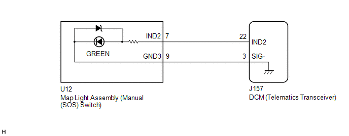
WIRING DIAGRAM
CAUTION / NOTICE / HINT
NOTICE:
Depending on the parts that are replaced during vehicle inspection or maintenance, performing initialization, registration or calibration may be needed. Refer to Precaution for Safety Connect System.
Click here .gif)
PROCEDURE
| 1. | CHECK DTC |
(a) Turn the engine switch off.
(b) Connect the Techstream to the DLC3.
(c) Turn the engine switch on (IG) and wait for 10 seconds or more.
(d) Turn the Techstream on.
(e) Clear the DTCs.
Body Electrical > Telematics > Clear DTCs(f) Check for DTCs and check that no DTCs are output.
Body Electrical > Telematics > Trouble CodesOK:
No DTCs are output.
| OK |  | USE SIMULATION METHOD TO CHECK |
|

| 2. | INSPECT MAP LIGHT ASSEMBLY (MANUAL (SOS) SWITCH) (GREEN INDICATOR) |
| (a) Remove the map light assembly (manual (SOS) switch). Click here |
|
(b) Connect 2 dry-cell batteries (1.5 V each) in series.
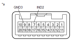
(c) Connect a positive (+) lead from batteries to terminal 7 (IND2) and a negative (-) lead to terminal 9 (GND3) of the map light assembly (manual (SOS) switch) connector.
(d) Check if the manual (SOS) switch green indicator comes on.
OK:
Manual (SOS) switch green indicator illuminates.
| NG | | REPLACE ROOF CONSOLE BOX ASSEMBLY (MANUAL [SOS] SWITCH) |
|
| 3. | CHECK HARNESS AND CONNECTOR (DCM (TELEMATICS TRANSCEIVER) - MAP LIGHT ASSEMBLY (MANUAL (SOS) SWITCH)) |
(a) Disconnect the J157 DCM (telematics transceiver) connector.
(b) Disconnect the U12 map light assembly (manual (SOS) switch) connector.
(c) Measure the resistance according to the value(s) in the table below.
Standard Resistance:
| Tester Connection | Condition | Specified Condition |
|---|---|---|
| J157-22 (IND2) - U12-7 (IND2) | Always | Below 1 Ω |
| J157-22 (IND2) or U12-7 (IND2) - Body ground | Always | 10 kΩ or higher |
| J157-3 (SIG-) - U12-9 (GND3) | Always | Below 1 Ω |
| J157-3 (SIG-) or U12-9 (GND3) - Body ground | Always | 10 kΩ or higher |
| NG | | REPAIR OR REPLACE HARNESS OR CONNECTOR |
|
| 4. | REPLACE DCM (TELEMATICS TRANSCEIVER) |
(a) Replace the DCM (telematics transceiver) with a new one.
Click here
NOTICE:
- The engine switch must be off.
- Do not exchange the DCM (telematics transceiver) with one from another vehicle.
| NEXT | | PERFORM DCM ACTIVATION |
 Indicator (Red) Circuit Short to Ground (B157011,B157013)
DESCRIPTION This DTC is stored when the DCM (telematics transceiver) detects an open or short in the manual (SOS) switch red indicator circuit of the manual (SOS) switch. The manual (SOS) switch red i ...
 Microphone Circuit Open (B157213)
DESCRIPTION This DTC is stored when the DCM (telematics transceiver) detects a malfunction in the telephone microphone assembly circuit. DTC No. Detection Item DTC Detection Condition Trouble ...
Other materials:
Lexus RX (RX 350L, RX450h) 2016-2026 Repair Manual > Yaw Rate And Acceleration Sensor: Removal
REMOVAL CAUTION / NOTICE / HINT The necessary procedures (adjustment, calibration, initialization, or registration) that must be performed after parts are removed, installed, or replaced during yaw rate sensor assembly removal/installation are shown below. Necessary Procedure After Parts Removed/Ins ...
Lexus RX (RX 350L, RX450h) 2016-2026 Repair Manual > Rear Center Seat Inner Belt Assembly(w/ Rear No. 2 Seat): Components
COMPONENTS ILLUSTRATION *1 CENTER SEAT HINGE COVER LH *2 NO. 1 RECLINING ADJUSTER RELEASE HANDLE RH *3 REAR CENTER SEAT INNER BELT ASSEMBLY *4 REAR SEAT COVER CAP RH *5 REAR SEAT LOCK CONTROL LEVER SUB-ASSEMBLY RH *6 SEPARATE TYPE REAR SEAT CUSHION COVER WITH PAD ...
Lexus RX (RX 350L, RX450h) 2016-{YEAR} Owners Manual
- For your information
- Pictorial index
- For safety and security
- Instrument cluster
- Operation of each component
- Driving
- Lexus Display Audio system
- Interior features
- Maintenance and care
- When trouble arises
- Vehicle specifications
- For owners
Lexus RX (RX 350L, RX450h) 2016-{YEAR} Repair Manual

0.0157