Lexus RX (RX 350L, RX450h) 2016-2026 Repair Manual: Emergency Call Switch Illumination Circuit
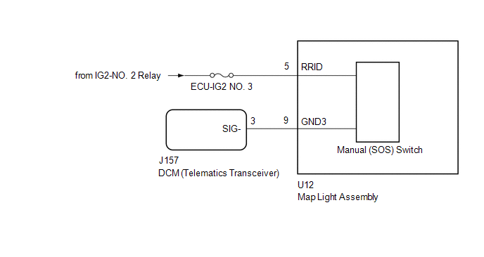
WIRING DIAGRAM
CAUTION / NOTICE / HINT
NOTICE:
-
Depending on the parts that are replaced during vehicle inspection or maintenance, performing initialization, registration or calibration may be needed. Refer to Precaution for Safety Connect System.
Click here
.gif)
- Inspect the fuses for circuits related to this system before performing the following procedure.
PROCEDURE
| 1. | CHECK HARNESS AND CONNECTOR (MAP LIGHT ASSEMBLY (MANUAL (SOS) SWITCH) POWER SOURCE) |
(a) Disconnect the J157 DCM (telematics transceiver) connector.
(b) Disconnect the U12 map light assembly (manual (SOS) switch) connector.
(c) Measure the voltage according to the value(s) in the table below.
Standard Voltage:
| Tester Connection | Switch Condition | Specified Condition |
|---|---|---|
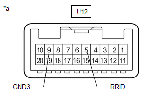
| U12-5 (RRID) - Body Ground | Engine switch on (IG) | 11 to 14 V |
(d) Measure the resistance according to the value(s) in the table below.
Standard Resistance:
| Tester Connection | Condition | Specified Condition |
|---|---|---|
| J157-3 (SIG-) - U12-9 (GND3) | Always | Below 1 Ω |
| J157-3 (SIG-) or U12-9 (GND3) - Body ground | Always | 10 kΩ or higher |
| NG | .gif) | REPAIR OR REPLACE HARNESS OR CONNECTOR |
|
.gif)
| 2. | INSPECT MAP LIGHT ASSEMBLY (MANUAL (SOS) SWITCH) |
| (a) Remove the map light assembly (manual (SOS) switch). Click here |
|
(b) Apply battery voltage to the connector and check that the roof console box assembly comes on.
OK:
| Measurement Condition | Condition | Specified Condition |
|---|---|---|
| Battery positive (+) → U12-5 (RRID) Battery negative (-) → U12-9 (GND3) | Always | Manual (SOS) switch illumination cones on |
| NG | | REPLACE MAP LIGHT ASSEMBLY (MANUAL (SOS) SWITCH) |
|
| 3. | REPLACE DCM (TELEMATICS TRANSCEIVER) |
(a) Replace the DCM (telematics transceiver) with a new one.
Click here
NOTICE:
- The engine switch must be off.
- Do not exchange the DCM (telematics transceiver) with one from another vehicle.
| NEXT | | PERFORM DCM ACTIVATION |
 Unable To Connect To Call Center
DESCRIPTION This may occur when the intensity of telephone radio frequency was very weak, or the safety connect system has a malfunction and a DTC is set. PROCEDURE 1. CHECK COMMUNICATION SERVIC ...

Other materials:
Lexus RX (RX 350L, RX450h) 2016-2026 Repair Manual > Steering Lock System: System Diagram
SYSTEM DIAGRAM Circuit Description Component Outline Steering Lock ECU (Steering Lock Actuator or Upper Bracket Assembly)
The steering is locked and unlocked by communicating with the certification ECU (smart key ECU assembly) and ID code box (immobiliser code ECU) via LIN communicati ...
Lexus RX (RX 350L, RX450h) 2016-2026 Repair Manual > Sfi System: Lost Communication with TCM Missing Message (U010187)
MONITOR DESCRIPTION The engine control unit and the transmission control unit are located inside the ECM. The engine control unit intercommunicates with the transmission control via CAN communication. If there is a problem in this communication, the ECM store this DTC. DTC No. Detection Item ...
Lexus RX (RX 350L, RX450h) 2016-{YEAR} Owners Manual
- For your information
- Pictorial index
- For safety and security
- Instrument cluster
- Operation of each component
- Driving
- Lexus Display Audio system
- Interior features
- Maintenance and care
- When trouble arises
- Vehicle specifications
- For owners
Lexus RX (RX 350L, RX450h) 2016-{YEAR} Repair Manual

0.0091