Lexus RX (RX 350L, RX450h) 2016-2026 Repair Manual: Removal
REMOVAL
CAUTION / NOTICE / HINT
The necessary procedures (adjustment, calibration, initialization, or registration) that must be performed after parts are removed and installed, or replaced during navigation antenna assembly removal/installation are shown below.
Necessary Procedures After Parts Removed/Installed/Replaced| Replaced Part or Performed Procedure | Necessary Procedure | Effect/Inoperative Function when Necessary Procedure not Performed | Link |
|---|---|---|---|
|
*1: When performing learning using the Techstream.
Click here | |||
| Disconnect cable from negative battery terminal | Memorize steering angle neutral point | Lane Control System | |
| Pre-collision System | |||
| Intelligent Clearance Sonar System*1 | |||
| Parking Assist Monitor System | | ||
| Panoramic View Monitor System | | ||
| Lighting System (w/ Automatic Headlight Beam Level Control System) | | ||
| Initialize back door lock | Power Door Lock Control System | | |
| Reset back door close position | Power Back Door System (w/ Outside Door Control Switch) | | |
| Removal/installation of the spiral cable with sensor sub-assembly |
| Parking assist monitor system | |
| Steering angle neutral point (Initialize panoramic view monitor system) | Panoramic view monitor system | | |
| Steering angle neutral point (Initialize intelligent clearance sonar system) | Intelligent clearance sonar system | | |
CAUTION:
Some of these service operations affect the SRS airbag system. Read the precautionary notices concerning the SRS airbag system before servicing.
Click here .gif)
.png)
PROCEDURE
1. REMOVE INSTRUMENT PANEL SAFETY PAD
Click here
2. REMOVE DEFROSTER NOZZLE ASSEMBLY
Click here
3. REMOVE NAVIGATION ANTENNA ASSEMBLY WITH BRACKET
| (a) Remove the 2 screws. |
|
.png)
| (b) Disengage the 2 claws. |
|
.png)
(c) Disconnect the connector to remove the navigation antenna assembly with bracket.
4. REMOVE NAVIGATION ANTENNA ASSEMBLY
(a) Disengage the 2 claws and 6 guides to remove the navigation antenna assembly as shown in the illustration.
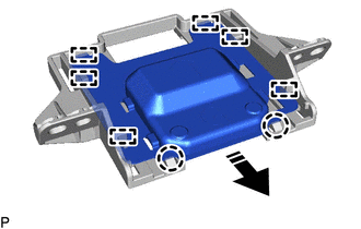
.png) | Remove in this Direction |
5. REMOVE NAVIGATION ANTENNA BRACKET
 Components
COMPONENTS ILLUSTRATION *1 DEFROSTER NOZZLE ASSEMBLY *2 NAVIGATION ANTENNA ASSEMBLY *3 NAVIGATION ANTENNA ASSEMBLY WITH BRACKET *4 NAVIGATION ANTENNA BRACKET ...
 Inspection
INSPECTION PROCEDURE 1. INSPECT NAVIGATION ANTENNA ASSEMBLY (w/o Manual (SOS) Switch) (a) Check that the navigation antenna assembly cable is properly installed and does not have any sharp bends, pinc ...
Other materials:
Lexus RX (RX 350L, RX450h) 2016-2026 Repair Manual > Towing Socket: Removal
REMOVAL CAUTION / NOTICE / HINT The necessary procedures (adjustment, calibration, initialization, or registration) that must be performed after parts are removed and installed, or replaced during rear bumper removal/installation are shown below. Necessary Procedures After Parts Removed/Installed/Re ...
Lexus RX (RX 350L, RX450h) 2016-2026 Repair Manual > Front Seatback Heater: Inspection
INSPECTION PROCEDURE 1. INSPECT FRONT SEATBACK HEATER ASSEMBLY (for LH Side) (a) Measure the resistance according to the value(s) in the table below. Standard Resistance: Tester Connection Condition Specified Condition 1 - 2 Seat heater temperature 20 °C (68 °F) 1.89 to 2.27 Ω ...
Lexus RX (RX 350L, RX450h) 2016-{YEAR} Owners Manual
- For your information
- Pictorial index
- For safety and security
- Instrument cluster
- Operation of each component
- Driving
- Lexus Display Audio system
- Interior features
- Maintenance and care
- When trouble arises
- Vehicle specifications
- For owners
Lexus RX (RX 350L, RX450h) 2016-{YEAR} Repair Manual

0.0124