Lexus RX (RX 350L, RX450h) 2016-2026 Repair Manual: Speaker Output Short (B15C3)
DESCRIPTION
This DTC is stored when a malfunction occurs in the speakers.
| DTC No. | Detection Item | DTC Detection Condition | Trouble Area |
|---|---|---|---|
| B15C3 | Speaker Output Short | A short is detected in the speaker output circuit |
|
WIRING DIAGRAM
for 9 Speakers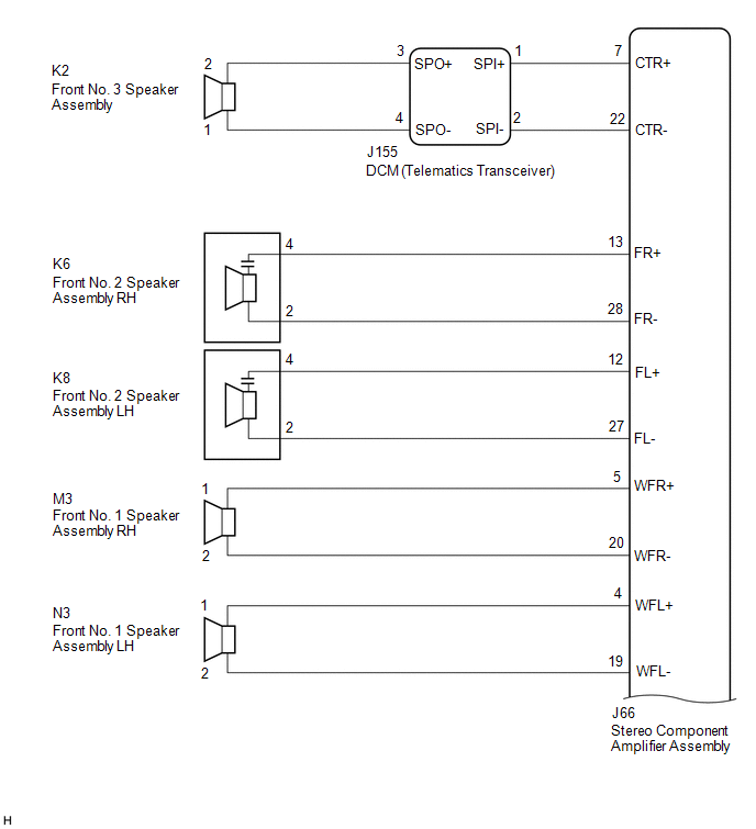 for 9 Speakers
 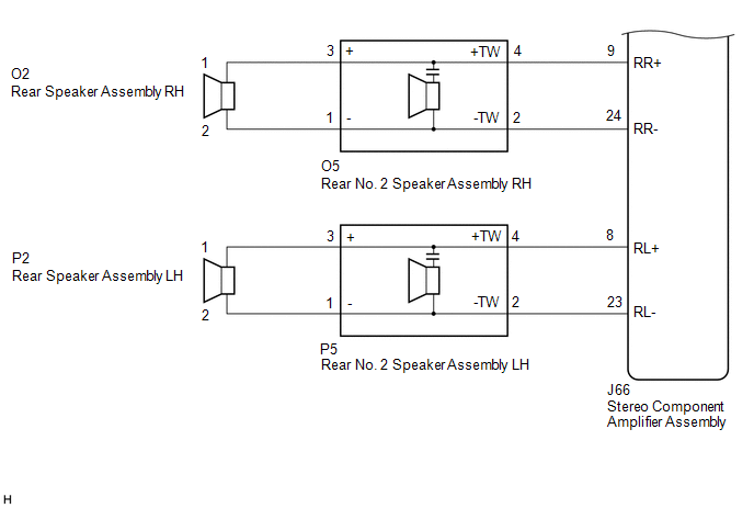 for 12 Speakers
 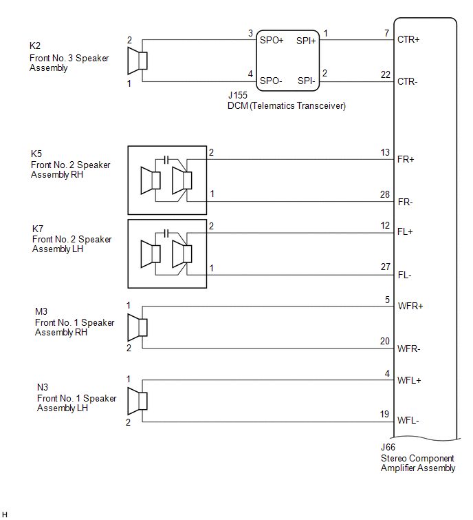 for 12 Speakers
 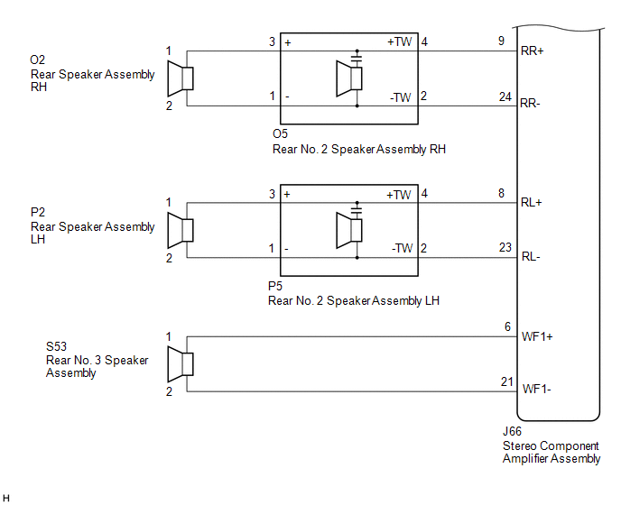 for 15 Speakers
 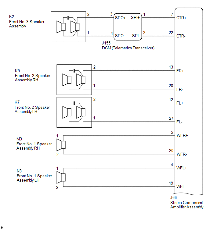 for 15 Speakers
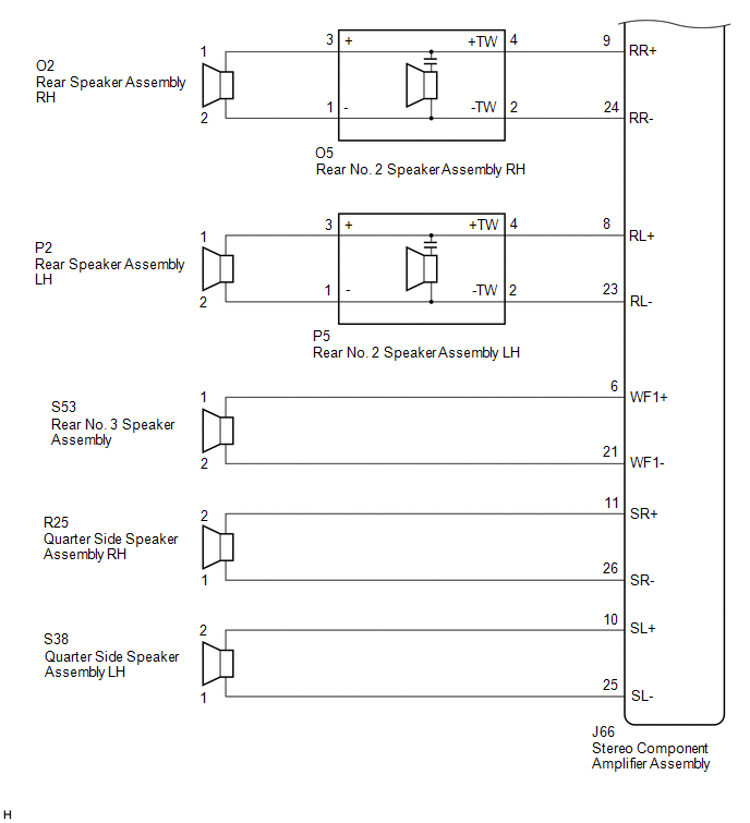
CAUTION / NOTICE / HINT
NOTICE:
Depending on the parts that are replaced during vehicle inspection or maintenance, performing initialization, registration or calibration may be needed. Refer to Precaution for Navigation System.
Click here .gif)
PROCEDURE
| 1. | CHECK MODEL |
(a) Choose the model to be inspected.
| Result | Proceed to |
|---|---|
| for 9 Speakers | A |
| for 12 Speakers | B |
| for 15 Speakers | C |
| B | .gif) | GO TO STEP 11 |
| C | | GO TO STEP 21 |
|
.gif)
| 2. | CHECK HARNESS AND CONNECTOR (STEREO COMPONENT AMPLIFIER ASSEMBLY, DCM (TELEMATICS TRANSCEIVER) OR SPEAKERS- BODY GROUND) |
(a) Disconnect the J66 stereo component amplifier assembly connector.
(b) Disconnect the J155 DCM (telematics transceiver) connector.
(c) Disconnect the K6 and K8 front No. 2 speaker assembly connectors.
(d) Disconnect the M3 and N3 front No. 1 speaker assembly connectors.
(e) Disconnect the O5 and P5 rear No. 2 speaker assembly connectors.
(f) Measure the resistance according to the value(s) in the table below.
Standard Resistance:
| Tester Connection | Condition | Specified Condition |
|---|---|---|
| J66-7 (CTR+) or J155-1 (SPI+) - Body ground | Always | 10 kΩ or higher |
| J66-22 (CTR-) or J155-2 (SPI-) - Body ground | Always | 10 kΩ or higher |
| J66-13 (FR+) or K6-4 - Body ground | Always | 10 kΩ or higher |
| J66-28 (FR-) or K6-2 - Body ground | Always | 10 kΩ or higher |
| J66-12 (FL+) or K8-4 - Body ground | Always | 10 kΩ or higher |
| J66-27 (FL-) or K8-2 - Body ground | Always | 10 kΩ or higher |
| J66-5 (WFR+) or M3-1 - Body ground | Always | 10 kΩ or higher |
| J66-20 (WFR-) or M3-2 - Body ground | Always | 10 kΩ or higher |
| J66-4 (WFL+) or N3-1 - Body ground | Always | 10 kΩ or higher |
| J66-19 (WFL-) or N3-2 - Body ground | Always | 10 kΩ or higher |
| J66-9 (RR+) or O5-4 (+TW) - Body ground | Always | 10 kΩ or higher |
| J66-24 (RR-) or O5-2 (-TW) - Body ground | Always | 10 kΩ or higher |
| J66-8 (RL+) or P5-4 (+TW) - Body ground | Always | 10 kΩ or higher |
| J66-23 (RL-) or P5-2 (-TW) - Body ground | Always | 10 kΩ or higher |
| NG | | REPAIR OR REPLACE HARNESS OR CONNECTOR |
|
| 3. | CHECK HARNESS AND CONNECTOR (DCM (TELEMATICS TRANSCEIVER) OR NO. 3 FRONT SPEAKER ASSEMBLY- BODY GROUND) |
(a) Disconnect the J155 DCM (telematics transceiver) connector.
(b) Disconnect the K2 front No. 3 speaker assembly connector.
(c) Measure the resistance according to the value(s) in the table below.
Standard Resistance:
| Tester Connection | Condition | Specified Condition |
|---|---|---|
| K2-2 or J155-3 (SPO+) - Body ground | Always | 10 kΩ or higher |
| K2-1 or J155-4 (SPO-) - Body ground | Always | 10 kΩ or higher |
| NG | | REPAIR OR REPLACE HARNESS OR CONNECTOR |
|
| 4. | INSPECT DCM (TELEMATICS TRANSCEIVER) |
(a) Remove the DCM (telematics transceiver).
Click here
| (b) Measure the resistance according to the value(s) in the table below. Standard Resistance:
|
|
.png)
| NG | | REPLACE DCM (TELEMATICS TRANSCEIVER) |
|
| 5. | CHECK HARNESS AND CONNECTOR (REAR SPEAKER ASSEMBLY OR REAR NO. 2 SPEAKER ASSEMBLY - BODY GROUND) |
(a) Disconnect the O2 and P2 rear speaker assembly connectors.
(b) Disconnect the O5 and P5 rear No. 2 speaker assembly connectors.
(c) Measure the resistance according to the value(s) in the table below.
Standard Resistance:
| Tester Connection | Condition | Specified Condition |
|---|---|---|
| O2-1 or O5-3 (+) - Body ground | Always | 10 kΩ or higher |
| O2-2 or O5-1 (-) - Body ground | Always | 10 kΩ or higher |
| P2-1 or P5-3 (+) - Body ground | Always | 10 kΩ or higher |
| P2-2 or P5-1 (-) - Body ground | Always | 10 kΩ or higher |
| NG | | REPAIR OR REPLACE HARNESS OR CONNECTOR |
|
| 6. | INSPECT FRONT NO. 3 SPEAKER ASSEMBLY |
(a) Remove the front No. 3 speaker assembly.
Click here
(b) Inspect the front No. 3 speaker assembly.
Click here
| NG | | REPLACE FRONT NO. 3 SPEAKER ASSEMBLY |
|
| 7. | INSPECT FRONT NO. 1 SPEAKER ASSEMBLY |
(a) Remove the front No. 1 speaker assembly.
Click here
(b) Inspect the front No. 1 speaker assembly.
Click here
| NG | | REPLACE FRONT NO. 1 SPEAKER ASSEMBLY |
|
| 8. | INSPECT REAR SPEAKER ASSEMBLY |
(a) Remove the rear speaker assembly.
Click here
(b) Inspect the rear speaker assembly.
Click here
| NG | | REPLACE REAR SPEAKER ASSEMBLY |
|
| 9. | INSPECT FRONT NO. 2 SPEAKER ASSEMBLY |
(a) Remove the front No. 2 speaker assembly.
Click here
(b) Inspect the front No. 2 speaker assembly.
Click here
(c) Clear the DTCs.
Body Electrical > Navigation System > Clear DTCs(d) Recheck for DTCs and check that no DTCs are output.
Body Electrical > Navigation System > Trouble CodesOK:
No DTCs are output.
| OK | | END |
|
| 10. | REPLACE REAR NO. 2 SPEAKER ASSEMBLY |
(a) Remove the rear No. 2 speaker assembly.
Click here
(b) Inspect the rear No. 2 speaker assembly.
Click here
(c) Clear the DTCs.
Body Electrical > Navigation System > Clear DTCs(d) Recheck for DTCs and check that no DTCs are output.
Body Electrical > Navigation System > Trouble CodesOK:
No DTCs are output.
| OK | | END |
| NG | | REPLACE STEREO COMPONENT AMPLIFIER ASSEMBLY |
| 11. | CHECK HARNESS AND CONNECTOR (STEREO COMPONENT AMPLIFIER ASSEMBLY, DCM (TELEMATICS TRANSCEIVER) OR SPEAKERS - BODY GROUND) |
(a) Disconnect the J66 stereo component amplifier assembly connector.
(b) Disconnect the J155 DCM (telematics transceiver) connector.
(c) Disconnect the K5 and K7 front No. 2 speaker assembly connectors.
(d) Disconnect the M3 and N3 front No. 1 speaker assembly connectors.
(e) Disconnect the O5 and P5 rear No. 2 speaker assembly connectors.
(f) Disconnect the S53 rear No. 3 speaker assembly connector.
(g) Measure the resistance according to the value(s) in the table below.
Standard Resistance:
| Tester Connection | Condition | Specified Condition |
|---|---|---|
| J66-7 (CTR+) or J155-1 (SPI+) - Body ground | Always | 10 kΩ or higher |
| J66-22 (CTR-) or J155-2 (SPI-) - Body ground | Always | 10 kΩ or higher |
| J66-13 (FR+) or K5-2 - Body ground | Always | 10 kΩ or higher |
| J66-28 (FR-) or K5-1 - Body ground | Always | 10 kΩ or higher |
| J66-12 (FL+) or K7-2 - Body ground | Always | 10 kΩ or higher |
| J66-27 (FL-) or K7-1 - Body ground | Always | 10 kΩ or higher |
| J66-5 (WFR+) or M3-1 - Body ground | Always | 10 kΩ or higher |
| J66-20 (WFR-) or M3-2 - Body ground | Always | 10 kΩ or higher |
| J66-4 (WFL+) or N3-1 - Body ground | Always | 10 kΩ or higher |
| J66-19 (WFL-) or N3-2 - Body ground | Always | 10 kΩ or higher |
| J66-9 (RR+) or O5-4 (+TW) - Body ground | Always | 10 kΩ or higher |
| J66-24 (RR-) or O5-2 (-TW) - Body ground | Always | 10 kΩ or higher |
| J66-8 (RL+) or P5-4 (+TW) - Body ground | Always | 10 kΩ or higher |
| J66-23 (RL-) or P5-2 (-TW) - Body ground | Always | 10 kΩ or higher |
| J66-6 (WF1+) or S53-1 - Body ground | Always | 10 kΩ or higher |
| J66-21 (WF1-) or S53-2 - Body ground | Always | 10 kΩ or higher |
| NG | | REPAIR OR REPLACE HARNESS OR CONNECTOR |
|
| 12. | CHECK HARNESS AND CONNECTOR (DCM (TELEMATICS TRANSCEIVER) OR FRONT NO. 3 SPEAKER ASSEMBLY- BODY GROUND) |
(a) Disconnect the J155 DCM (telematics transceiver) connector.
(b) Disconnect the K2 front No. 3 speaker assembly connector.
(c) Measure the resistance according to the value(s) in the table below.
Standard Resistance:
| Tester Connection | Condition | Specified Condition |
|---|---|---|
| K2-2 or J155-3 (SPO+) - Body ground | Always | 10 kΩ or higher |
| K2-1 or J155-4 (SPO-) - Body ground | Always | 10 kΩ or higher |
| NG | | REPAIR OR REPLACE HARNESS OR CONNECTOR |
|
| 13. | INSPECT DCM (TELEMATICS TRANSCEIVER) |
(a) Remove the DCM (telematics transceiver).
Click here
| (b) Measure the resistance according to the value(s) in the table below. Standard Resistance:
|
|
| NG | | REPLACE DCM (TELEMATICS TRANSCEIVER) |
|
| 14. | CHECK HARNESS AND CONNECTOR (REAR SPEAKER ASSEMBLY OR REAR NO. 2 SPEAKER ASSEMBLY - BODY GROUND) |
(a) Disconnect the O2 and P2 rear speaker assembly connectors.
(b) Disconnect the O5 and P5 rear No. 2 speaker assembly connectors.
(c) Measure the resistance according to the value(s) in the table below.
Standard Resistance:
| Tester Connection | Condition | Specified Condition |
|---|---|---|
| O2-1 or O5-3 (+) - Body ground | Always | 10 kΩ or higher |
| O2-2 or O5-1 (-) - Body ground | Always | 10 kΩ or higher |
| P2-1 or P5-3 (+) - Body ground | Always | 10 kΩ or higher |
| P2-2 or P5-1 (-) - Body ground | Always | 10 kΩ or higher |
| NG | | REPAIR OR REPLACE HARNESS OR CONNECTOR |
|
| 15. | INSPECT FRONT NO. 3 SPEAKER ASSEMBLY |
(a) Remove the front No. 3 speaker assembly.
Click here
(b) Inspect the front No. 3 speaker assembly.
Click here
| NG | | REPLACE FRONT NO. 3 SPEAKER ASSEMBLY |
|
| 16. | INSPECT FRONT NO. 1 SPEAKER ASSEMBLY |
(a) Remove the front No. 1 speaker assembly.
Click here
(b) Inspect the front No. 1 speaker assembly.
Click here
| NG | | REPLACE FRONT NO. 1 SPEAKER ASSEMBLY |
|
| 17. | INSPECT REAR SPEAKER ASSEMBLY |
(a) Remove the rear speaker assembly.
Click here
(b) Inspect the rear speaker assembly.
Click here
| NG | | REPLACE REAR SPEAKER ASSEMBLY |
|
| 18. | INSPECT REAR NO. 3 SPEAKER ASSEMBLY |
(a) Remove the rear No. 3 speaker assembly.
w/o Rear No. 2 Seat: Click here
w/ Rear No. 2 Seat: Click here
(b) Inspect the rear No. 3 speaker assembly.
w/o Rear No. 2 Seat: Click here
w/ Rear No. 2 Seat: Click here
| NG | | REPLACE REAR NO. 3 SPEAKER ASSEMBLY |
|
| 19. | INSPECT REAR NO. 2 SPEAKER ASSEMBLY |
(a) Remove the rear No. 2 speaker assembly.
Click here
(b) Inspect the rear No. 2 speaker assembly.
Click here
(c) Clear the DTCs.
Body Electrical > Navigation System > Clear DTCs(d) Recheck for DTCs and check that no DTCs are output.
Body Electrical > Navigation System > Trouble CodesOK:
No DTCs are output.
| OK | | END |
|
| 20. | REPLACE FRONT NO. 2 SPEAKER ASSEMBLY |
(a) Remove the front No. 2 speaker assembly.
Click here
(b) Inspect the front No. 2 speaker assembly.
Click here
(c) Clear the DTCs.
Body Electrical > Navigation System > Clear DTCs(d) Recheck for DTCs and check that no DTCs are output.
Body Electrical > Navigation System > Trouble CodesOK:
No DTCs are output.
| OK | | END |
| NG | | REPLACE STEREO COMPONENT AMPLIFIER ASSEMBLY |
| 21. | CHECK HARNESS AND CONNECTOR (STEREO COMPONENT AMPLIFIER ASSEMBLY, DCM (TELEMATICS TRANSCEIVER) OR SPEAKERS - BODY GROUND) |
(a) Disconnect the J66 stereo component amplifier assembly connector.
(b) Disconnect the J155 DCM (telematics transceiver) connector.
(c) Disconnect the K5 and K7 front No. 2 speaker assembly connectors.
(d) Disconnect the M3 and N3 front No. 1 speaker assembly connectors.
(e) Disconnect the O5 and P5 rear No. 2 speaker assembly connectors.
(f) Disconnect the S53 rear No. 3 speaker assembly connector.
(g) Disconnect the R25 and S38 quarter side speaker assembly connectors.
(h) Measure the resistance according to the value(s) in the table below.
Standard Resistance:
| Tester Connection | Condition | Specified Condition |
|---|---|---|
| J66-7 (CTR+) or J155-1 (SPI+) - Body ground | Always | 10 kΩ or higher |
| J66-22 (CTR-) or J155-2 (SPI-) - Body ground | Always | 10 kΩ or higher |
| J66-13 (FR+) or K5-2 - Body ground | Always | 10 kΩ or higher |
| J66-28 (FR-) or K5-1 - Body ground | Always | 10 kΩ or higher |
| J66-12 (FL+) or K7-2 - Body ground | Always | 10 kΩ or higher |
| J66-27 (FL-) or K7-1 - Body ground | Always | 10 kΩ or higher |
| J66-5 (WFR+) or M3-1 - Body ground | Always | 10 kΩ or higher |
| J66-20 (WFR-) or M3-2 - Body ground | Always | 10 kΩ or higher |
| J66-4 (WFL+) or N3-1 - Body ground | Always | 10 kΩ or higher |
| J66-19 (WFL-) or N3-2 - Body ground | Always | 10 kΩ or higher |
| J66-9 (RR+) or O5-4 (+TW) - Body ground | Always | 10 kΩ or higher |
| J66-24 (RR-) or O5-2 (-TW) - Body ground | Always | 10 kΩ or higher |
| J66-8 (RL+) or P5-4 (+TW) - Body ground | Always | 10 kΩ or higher |
| J66-23 (RL-) or P5-2 (-TW) - Body ground | Always | 10 kΩ or higher |
| J66-6 (WF1+) or S53-1 - Body ground | Always | 10 kΩ or higher |
| J66-21 (WF1-) or S53-2 - Body ground | Always | 10 kΩ or higher |
| J66-11 (SR+) or R25-2 - Body ground | Always | 10 kΩ or higher |
| J66-26 (SR-) or R25-1 - Body ground | Always | 10 kΩ or higher |
| J66-10 (SL+) or S38-2 - Body ground | Always | 10 kΩ or higher |
| J66-25 (SL-) or S38-1 - Body ground | Always | 10 kΩ or higher |
| NG | | REPAIR OR REPLACE HARNESS OR CONNECTOR |
|
| 22. | CHECK HARNESS AND CONNECTOR (DCM (TELEMATICS TRANSCEIVER) OR FRONT NO. 3 SPEAKER ASSEMBLY- BODY GROUND) |
(a) Disconnect the J155 DCM (telematics transceiver) connector.
(b) Disconnect the K2 front No. 3 speaker assembly connector.
(c) Measure the resistance according to the value(s) in the table below.
Standard Resistance:
| Tester Connection | Condition | Specified Condition |
|---|---|---|
| K2-2 or J155-3 (SPO+) - Body ground | Always | 10 kΩ or higher |
| K2-1 or J155-4 (SPO-) - Body ground | Always | 10 kΩ or higher |
| NG | | REPAIR OR REPLACE HARNESS OR CONNECTOR |
|
| 23. | INSPECT DCM (TELEMATICS TRANSCEIVER) |
(a) Remove the DCM (telematics transceiver).
Click here
| (b) Measure the resistance according to the value(s) in the table below. Standard Resistance:
|
|
| NG | | REPLACE DCM (TELEMATICS TRANSCEIVER) |
|
| 24. | CHECK HARNESS AND CONNECTOR (REAR SPEAKER ASSEMBLY OR REAR NO. 2 SPEAKER ASSEMBLY - BODY GROUND) |
(a) Disconnect the O2 and P2 rear speaker assembly connectors.
(b) Disconnect the O5 and P5 rear No. 2 speaker assembly connectors.
(c) Measure the resistance according to the value(s) in the table below.
Standard Resistance:
| Tester Connection | Condition | Specified Condition |
|---|---|---|
| O2-1 or O5-3 (+) - Body ground | Always | 10 kΩ or higher |
| O2-2 or O5-1 (-) - Body ground | Always | 10 kΩ or higher |
| P2-1 or P5-3 (+) - Body ground | Always | 10 kΩ or higher |
| P2-2 or P5-1 (-) - Body ground | Always | 10 kΩ or higher |
| NG | | REPAIR OR REPLACE HARNESS OR CONNECTOR |
|
| 25. | INSPECT FRONT NO. 1 SPEAKER ASSEMBLY |
(a) Remove the front No. 1 speaker assembly.
Click here
(b) Inspect the front No. 1 speaker assembly.
Click here
| NG | | REPLACE FRONT NO. 1 SPEAKER ASSEMBLY |
|
| 26. | INSPECT REAR SPEAKER ASSEMBLY |
(a) Remove the rear speaker assembly.
Click here
(b) Inspect the rear speaker assembly.
Click here
| NG | | REPLACE REAR SPEAKER ASSEMBLY |
|
| 27. | INSPECT REAR NO.3 SPEAKER ASSEMBLY |
(a) Remove the rear No. 3 speaker assembly.
w/o Rear No. 2 Seat: Click here
w/ Rear No. 2 Seat: Click here
(b) Inspect the rear No. 3 speaker assembly.
w/o Rear No. 2 Seat: Click here
w/ Rear No. 2 Seat: Click here
| NG | | REPLACE REAR NO. 3 SPEAKER ASSEMBLY |
|
| 28. | INSPECT QUARTER SIDE SPEAKER ASSEMBLY |
(a) Remove the quarter side speaker assembly.
w/o Rear No. 2 Seat: Click here
w/ Rear No. 2 Seat: Click here
(b) Inspect the quarter side speaker assembly.
w/o Rear No. 2 Seat: Click here
w/ Rear No. 2 Seat: Click here
| NG | | REPLACE QUARTER SIDE SPEAKER ASSEMBLY |
|
| 29. | INSPECT REAR NO. 2 SPEAKER ASSEMBLY |
(a) Remove the rear No. 2 speaker assembly.
Click here
(b) Inspect the rear No. 2 speaker assembly.
Click here
(c) Clear the DTCs.
Body Electrical > Navigation System > Clear DTCs(d) Recheck for DTCs and check that no DTCs are output.
Body Electrical > Navigation System > Trouble CodesOK:
No DTCs are output.
| OK | | END |
|
| 30. | REPLACE FRONT NO. 2 SPEAKER ASSEMBLY |
(a) Remove the front No. 2 speaker assembly.
Click here
(b) Inspect the front No. 2 speaker assembly.
Click here
(c) Clear the DTCs.
Body Electrical > Navigation System > Clear DTCs(d) Recheck for DTCs and check that no DTCs are output.
Body Electrical > Navigation System > Trouble CodesOK:
No DTCs are output.
| OK | | END |
|
| 31. | REPLACE FRONT NO. 3 SPEAKER ASSEMBLY |
(a) Remove the front No. 3 speaker assembly.
Click here
(b) Inspect the front No. 3 speaker assembly.
Click here
(c) Clear the DTCs.
Body Electrical > Navigation System > Clear DTCs(d) Recheck for DTCs and check that no DTCs are output.
Body Electrical > Navigation System > Trouble CodesOK:
No DTCs are output.
| OK | | END |
| NG | | REPLACE STEREO COMPONENT AMPLIFIER ASSEMBLY |
 Speed Signal Malfunction (B15C2)
DESCRIPTION The navigation ECU receives a vehicle speed signal from the combination meter assembly and information from the navigation antenna assembly, and then adjusts the vehicle position on the ma ...
 MOST Communication Malfunction (B15D0)
DESCRIPTION Navigation system components communicate with each other via MOST communication. If a line short or short to ground occurs in a MOST communication line, communication will not be possible ...
Other materials:
Lexus RX (RX 350L, RX450h) 2016-2026 Repair Manual > Charging System: On-vehicle Inspection
ON-VEHICLE INSPECTION PROCEDURE 1. CHECK BATTERY CONDITION NOTICE: If the battery is weak or if the engine is difficult to start, recharge the battery and perform inspections again before returning the vehicle to the customer. (a) Check the battery for damage or deformation. If severe damage, deform ...
Lexus RX (RX 350L, RX450h) 2016-2026 Repair Manual > Sfi System: Transmission Range Sensor "A" Circuit Open (P070513,P070562)
DESCRIPTION The park/neutral position switch assembly detects the shift lever position and sends signals to the ECM. DTC No. Detection Item DTC Detection Condition Trouble Area MIL Memory Note P070513 Transmission Range Sensor "A" Circuit Open All switches are off simultaneous ...
Lexus RX (RX 350L, RX450h) 2016-{YEAR} Owners Manual
- For your information
- Pictorial index
- For safety and security
- Instrument cluster
- Operation of each component
- Driving
- Lexus Display Audio system
- Interior features
- Maintenance and care
- When trouble arises
- Vehicle specifications
- For owners
Lexus RX (RX 350L, RX450h) 2016-{YEAR} Repair Manual

0.0106