Lexus RX (RX 350L, RX450h) 2016-2026 Repair Manual: Speed Signal Malfunction (B15C2)
DESCRIPTION
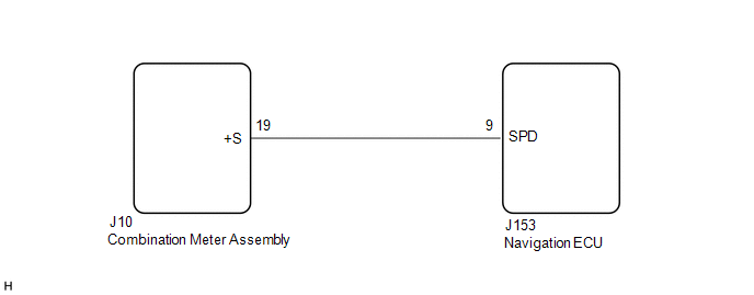
The navigation ECU receives a vehicle speed signal from the combination meter assembly and information from the navigation antenna assembly, and then adjusts the vehicle position on the map.
The navigation ECU stores this DTC when the difference between the speed information that the navigation antenna assembly receives and the SPD pulse received from the combination meter assembly becomes large.
HINT:
- A voltage of 12 V or 5 V is output from each ECU and then input to the combination meter assembly. The signal is changed to a pulse signal at the transistor in the combination meter assembly. Each ECU controls its respective system based on this pulse signal.
- If a short occurs in any of the ECUs or in the wire harness connected to an ECU, all systems in the following diagram will not operate normally.
| DTC No. | Detection Item | DTC Detection Condition | Trouble Area |
|---|---|---|---|
| B15C2 | Speed Signal Malfunction | A difference between the GPS speed and SPD pulse is detected |
|
WIRING DIAGRAM
CAUTION / NOTICE / HINT
NOTICE:
Depending on the parts that are replaced during vehicle inspection or maintenance, performing initialization, registration or calibration may be needed. Refer to Precaution for Navigation System.
Click here .gif)
PROCEDURE
| 1. | CHECK DTC |
(a) Clear the DTCs.
Body Electrical > Navigation System > Clear DTCs(b) Recheck for DTCs and check that no DTCs are output.
Body Electrical > Navigation System > Trouble CodesOK:
No DTCs are output.
| OK | .gif) | USE SIMULATION METHOD TO CHECK |
|
.gif)
| 2. | CHECK VEHICLE SENSOR (OPERATION CHECK) |
| (a) Enter the "System Sensors Check" screen. Refer to Check GPS & Vehicle Sensors in Operation Check. Click here |
|
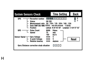
(b) While driving the vehicle, compare the "Speed" indicator to the reading on the speedometer. Check if these readings are almost equal.
HINT:
The combination meter assembly receives the vehicle speed signal from the skid control ECU via CAN communication. Therefore, perform the following procedure inspection referring to values in the Data List of the skid control ECU because it is the source of the vehicle speed signal.
OK:
Vehicle speed displayed on the "System Sensors Check" screen is almost the same as the actual vehicle speed measured using the Techstream.
Click here
| OK | | GO TO STEP 5 |
|
| 3. | CHECK COMBINATION METER ASSEMBLY (OUTPUT WAVEFORM) |
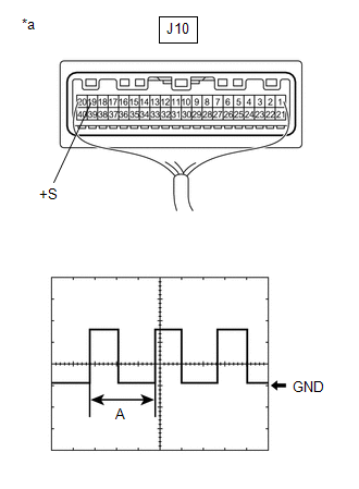
| (a) Check the output waveform. (1) Remove the combination meter assembly with the connector(s) still connected. (2) Connect an oscilloscope to terminal J10-19 (+S) and body ground. (3) Turn the engine switch on (IG). (4) Turn a wheel slowly. (5) Check the signal waveform according to the condition(s) in the table below.
OK: The waveform is similar to that shown in the illustration. HINT: When the system is functioning normally, one wheel revolution generates 4 pulses. As the vehicle speed increases, the width indicated by (A) in the illustration narrows. |
|
| NG | | GO TO METER / GAUGE SYSTEM |
|
| 4. | INSPECT NAVIGATION ECU (INPUT WAVEFORM) |
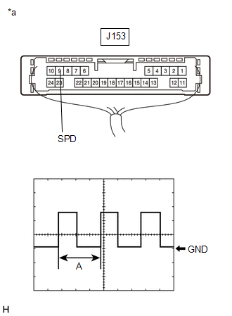
| (a) Check the input waveform. (1) Remove the navigation ECU with the connector(s) still connected. (2) Connect an oscilloscope to terminal J153-9 (SPD) and body ground. (3) Turn the engine switch on (IG). (4) Turn a wheel slowly. (5) Check the signal waveform according to the condition(s) in the table below.
OK: The waveform is similar to that shown in the illustration. HINT: When the system is functioning normally, one wheel revolution generates 4 pulses. As the vehicle speed increases, the width indicated by (A) in the illustration narrows. |
|
| NG | | REPAIR OR REPLACE HARNESS OR CONNECTOR |
|
| 5. | REPLACE NAVIGATION ECU |
(a) Replace the navigation ECU with a new or known good one.
Click here
|
| 6. | CHECK DTC |
(a) Clear the DTCs.
Body Electrical > Navigation System > Clear DTCs(b) Recheck for DTCs and check that no DTCs are output.
Body Electrical > Navigation System > Trouble CodesOK:
No DTCs are output.
| OK | | END (NAVIGATION ECU IS DEFECTIVE) |
| NG | | REPLACE RADIO RECEIVER ASSEMBLY |
 GPS Antenna Connection Malfunction(short) (B15C0,B15C1)
DESCRIPTION These DTCs are stored when a malfunction occurs in the navigation antenna assembly. DTC No. Detection Item DTC Detection Condition Trouble Area B15C0 GPS Antenna Connection ...
 Speaker Output Short (B15C3)
DESCRIPTION This DTC is stored when a malfunction occurs in the speakers. DTC No. Detection Item DTC Detection Condition Trouble Area B15C3 Speaker Output Short A short is detected in ...
Other materials:
Lexus RX (RX 350L, RX450h) 2016-2026 Repair Manual > Sfi System: Readiness Monitor Drive Pattern
READINESS MONITOR DRIVE PATTERN PURPOSE OF READINESS TESTS
The On-Board Diagnostic (OBD II) system is designed to monitor the performance of emission related components, and indicate any detected abnormalities using DTCs (Diagnostic Trouble Codes). Since various components need to be monitored du ...
Lexus RX (RX 350L, RX450h) 2016-2026 Repair Manual > 2gr-fks (starting): Starting System
Parts LocationPARTS LOCATION ILLUSTRATION *1 STARTER ASSEMBLY *2 ECM *3 ENGINE ROOM RELAY BLOCK ASSEMBLY - ST RELAY - ST NO. 1 FUSE *4 PARK/NEUTRAL POSITION SWITCH ASSEMBLY ILLUSTRATION *1 ENGINE SWITCH *2 CERTIFICATION ECU (SMART KEY ECU ASSEMBLY) System DiagramS ...
Lexus RX (RX 350L, RX450h) 2016-{YEAR} Owners Manual
- For your information
- Pictorial index
- For safety and security
- Instrument cluster
- Operation of each component
- Driving
- Lexus Display Audio system
- Interior features
- Maintenance and care
- When trouble arises
- Vehicle specifications
- For owners
Lexus RX (RX 350L, RX450h) 2016-{YEAR} Repair Manual

0.0112