Lexus RX (RX 350L, RX450h) 2016-2026 Repair Manual: Removal
REMOVAL
CAUTION / NOTICE / HINT
The necessary procedures (adjustment, calibration, initialization or registration) that must be performed after parts are removed and installed, or replaced during starter assembly removal/installation are shown below.
Necessary Procedures After Parts Removed/Installed/Replaced| Replaced Part or Performed Procedure | Necessary Procedure | Effect/Inoperative Function when Necessary Procedure not Performed | Link |
|---|---|---|---|
| Battery terminal is disconnected/reconnected | Memorize steering angle neutral point | Lane Control System | |
| Pre-collision system | |||
| Intelligent clearance sonar system*1 | |||
| Parking assist monitor system | | ||
| Panoramic view monitor system | | ||
| Lighting system (w/ Automatic Headlight Beam Level Control System) | | ||
| Initialize back door lock | Power door lock control system | | |
| Reset back door close position | Power Back Door System (w/ Outside Door Control Switch) | |
*1: When performing learning using the Techstream.
Click here .gif)
PROCEDURE
1. PRECAUTION
NOTICE:
After turning the engine switch off, waiting time may be required before disconnecting the cable from the negative (-) battery terminal. Therefore, make sure to read the disconnecting the cable from the negative (-) battery terminal notices before proceeding with work.
Click here
2. DISCONNECT CABLE FROM NEGATIVE BATTERY TERMINAL
NOTICE:
When disconnecting the cable, some systems need to be initialized after the cable is reconnected.
Click here
3. REMOVE COOL AIR INTAKE DUCT SEAL
Click here
4. REMOVE INLET AIR CLEANER ASSEMBLY
Click here
5. REMOVE AIR CLEANER CAP WITH AIR CLEANER HOSE
Click here
6. REMOVE AIR CLEANER FILTER ELEMENT SUB-ASSEMBLY
Click here
7. REMOVE AIR CLEANER CASE SUB-ASSEMBLY
Click here
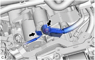
8. DISCONNECT TRANSMISSION CONTROL CABLE ASSEMBLY
| (a) Using a screwdriver, disengage the 4 claws and disconnect the transmission control cable assembly with clip from the No. 1 transmission control cable bracket. |
|
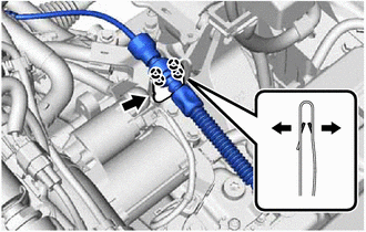
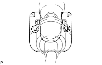
| (b) Using a screwdriver, disengage the 2 claws and remove the clip from the transmission control cable assembly. |
|
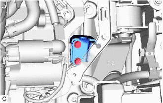
9. REMOVE NO. 1 TRANSMISSION CONTROL CABLE BRACKET
| (a) Remove the 2 bolts and No. 1 transmission control cable bracket. |
|
10. REMOVE STARTER ASSEMBLY
| (a) Remove the terminal cap. |
|
(b) Remove the nut and disconnect terminal 30.
(c) Disconnect the starter assembly connector.
| (d) Remove the 2 bolts and separate the wire harness. |
|

| (e) Remove the 2 bolts and starter assembly. |
|

 Components
COMPONENTS ILLUSTRATION *A Type A *B Type B *1 AIR CLEANER CAP SUB-ASSEMBLY *2 AIR CLEANER CASE SUB-ASSEMBLY *3 AIR CLEANER FILTER ELEMENT SUB-ASSEMBLY *4 COOL AIR INTAKE ...
 Disassembly
DISASSEMBLY PROCEDURE 1. REMOVE MAGNET STARTER SWITCH ASSEMBLY (a) Remove the nut and disconnect the field coil lead wire from terminal C. (b) While holding the magnet starter switch ...
Other materials:
Lexus RX (RX 350L, RX450h) 2016-2026 Repair Manual > U881e (automatic Transmission / Transaxle): Transmission Wire
ComponentsCOMPONENTS ILLUSTRATION *1 TRANSMISSION WIRE - - Tightening torque for "Major areas involving basic vehicle performance such as moving/turning/stopping": N*m (kgf*cm, ft.*lbf) ATF WS RemovalREMOVAL PROCEDURE 1. REMOVE TRANSMISSION VALVE BODY ASSEMBLY Click here ...
Lexus RX (RX 350L, RX450h) 2016-2026 Repair Manual > Emission Control System: Parts Location
PARTS LOCATION ILLUSTRATION *1 CANISTER (CHARCOAL CANISTER ASSEMBLY) *2 FUEL TANK CAP ASSEMBLY *3 PCV VALVE (VENTILATION VALVE SUB-ASSEMBLY) *4 PURGE VALVE (PURGE VSV) *5 ECM *6 NO. 1 ENGINE ROOM RELAY BLOCK AND NO. 1 JUNCTION BLOCK ASSEMBLY - EFI MAIN RELAY - EFI-MAIN ...
Lexus RX (RX 350L, RX450h) 2016-{YEAR} Owners Manual
- For your information
- Pictorial index
- For safety and security
- Instrument cluster
- Operation of each component
- Driving
- Lexus Display Audio system
- Interior features
- Maintenance and care
- When trouble arises
- Vehicle specifications
- For owners
Lexus RX (RX 350L, RX450h) 2016-{YEAR} Repair Manual

0.0101