Lexus RX (RX 350L, RX450h) 2016-2026 Repair Manual: Disassembly
DISASSEMBLY
PROCEDURE
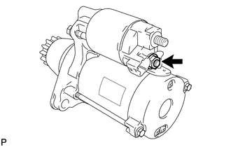
1. REMOVE MAGNET STARTER SWITCH ASSEMBLY
| (a) Remove the nut and disconnect the field coil lead wire from terminal C. |
|
| (b) While holding the magnet starter switch assembly to the starter drive housing assembly, remove the 2 nuts. |
|
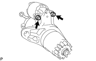
(c) Remove the magnet starter switch assembly from the starter drive housing assembly.
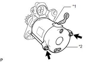
2. REMOVE STARTER YOKE ASSEMBLY
| (a) Remove the 2 through bolts and pull out the starter yoke assembly together with the starter commutator end frame assembly. |
|
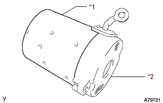
3. REMOVE STARTER COMMUTATOR END FRAME ASSEMBLY
| (a) Remove the starter commutator end frame assembly from the starter yoke assembly. |
|
4. REMOVE STARTER ARMATURE PLATE
| (a) Remove the starter armature plate from the starter yoke assembly. |
|
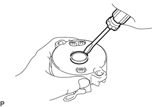
5. REMOVE STARTER COMMUTATOR END FRAME COVER
| (a) Using a screwdriver, pry out the starter commutator end frame cover from the starter commutator end frame assembly. |
|
6. REMOVE STARTER ARMATURE ASSEMBLY
| (a) Secure the starter commutator end frame assembly in a vise between aluminum plates. NOTICE: Do not overtighten the vise. |
|
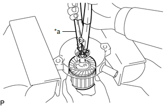
(b) Using snap ring pliers, remove the snap ring and washer.
NOTICE:
Do not drop the starter armature assembly.
(c) Remove the starter armature assembly from the starter commutator end frame assembly.
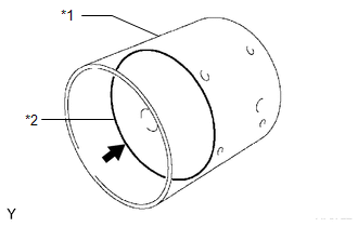
7. REMOVE RUBBER SEAL
| (a) Remove the rubber seal from the starter drive housing assembly. |
|
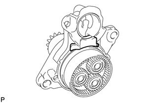
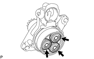
8. REMOVE PLANETARY GEAR
| (a) Remove the 3 planetary gears from the starter drive housing assembly. |
|
 Removal
REMOVAL CAUTION / NOTICE / HINT The necessary procedures (adjustment, calibration, initialization or registration) that must be performed after parts are removed and installed, or replaced during star ...
 Inspection
INSPECTION PROCEDURE 1. INSPECT STARTER ASSEMBLY CAUTION: As a large electric current passes through the cable during this inspection, a thick cable must be used. If not, the cable may become hot and ...
Other materials:
Lexus RX (RX 350L, RX450h) 2016-2026 Repair Manual > Rear Door Speaker: Inspection
INSPECTION PROCEDURE 1. INSPECT REAR SPEAKER ASSEMBLY (a) With the speaker installed, check that there is no looseness or other abnormalities. (b) Check that there is no foreign matter in the speaker, no tears on the speaker cone or other abnormalities. (c) Measure the resistance of the speaker. ...
Lexus RX (RX 350L, RX450h) 2016-2026 Repair Manual > Sfi System: Terminals Of Ecm
TERMINALS OF ECM HINT: The standard voltage, resistance and waveform between each pair of the ECM terminals is shown in the table below. The appropriate conditions for checking each pair of the terminals is also indicated. The result of checks should be compared with the standard voltage, resistanc ...
Lexus RX (RX 350L, RX450h) 2016-{YEAR} Owners Manual
- For your information
- Pictorial index
- For safety and security
- Instrument cluster
- Operation of each component
- Driving
- Lexus Display Audio system
- Interior features
- Maintenance and care
- When trouble arises
- Vehicle specifications
- For owners
Lexus RX (RX 350L, RX450h) 2016-{YEAR} Repair Manual

0.0187