Lexus RX (RX 350L, RX450h) 2016-2026 Repair Manual: Inspection
INSPECTION
PROCEDURE
1. INSPECT STARTER ASSEMBLY
CAUTION:
As a large electric current passes through the cable during this inspection, a thick cable must be used. If not, the cable may become hot and cause injury.
NOTICE:
Perform each of the following tests within 3 to 5 seconds to prevent the coil from burning out.
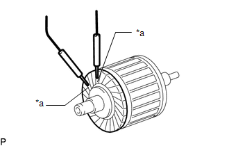
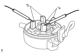
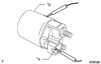
(a) Perform a pull-in test.
(1) Remove the nut, and disconnect the field coil lead wire from terminal C.
(2) Connect a battery to the magnet switch as shown in the illustration. Check that the clutch pinion gear moves outward.
If the clutch pinion gear does not move outward, replace the magnet starter switch assembly.
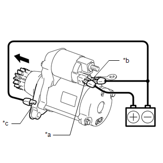
| *a | Terminal 50 |
| *b | Terminal C |
| *c | Starter Body |
.png) | Moves outward |
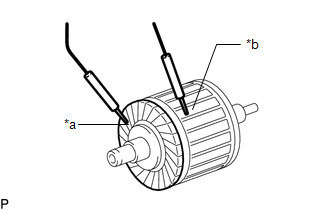
(b) Perform a hold-in test.
(1) While maintaining the battery connections of the pull-in test, disconnect the negative (-) lead from terminal C. Check that the clutch pinion gear does not return inward.
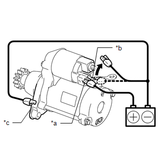
| *a | Terminal 50 |
| *b | Terminal C |
| *c | Starter Body |
| | Disconnect |
If the clutch pinion gear returns inward, replace the magnet starter switch assembly.
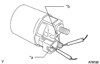
(c) Perform a return test.
(1) Disconnect the negative (-) lead from the starter body. Check that the clutch pinion gear returns inward.
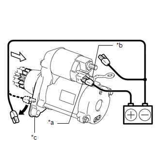
| *a | Terminal 50 |
| *b | Terminal C |
| *c | Starter Body |
| | Disconnect |
.png) | Returns inward |
If the clutch pinion gear does not return inward, replace the magnet starter switch assembly.
(d) Perform a no-load performance test.
(1) Connect the field coil lead wire to terminal C with the nut. Make sure that the field coil lead wire is not grounded.
Torque:
10 N·m {102 kgf·cm, 7 ft·lbf}
(2) Secure the starter assembly in a vise between aluminum plates.
NOTICE:
Ensure that the starter assembly is secured in the vise to prevent it from falling out.
(3) Connect the battery and an ammeter to the starter assembly as shown in the illustration.
NOTICE:
Do not allow any lead to get caught as the clutch pinion gear operates.
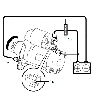
| *a | Terminal 50 |
| *b | Terminal 30 |
| *c | Starter Body |
| | Rotates |
(4) Check that the starter assembly operates smoothly and steadily while the clutch pinion gear is moving outward.
Measure the current according to the value(s) in the table below.
Standard Current:
| Tester Connection | Condition | Specified Condition |
|---|---|---|
| Battery positive (+) terminal - Terminal 30 - Terminal 50 | 11.5 V | Below 90 A |
If the result is not as specified, replace the starter assembly.
2. INSPECT STARTER ARMATURE ASSEMBLY
HINT:
If there is no continuity between any segments, replace the starter armature assembly.
(a) Check the commutator appearance.
If the surface is dirty or burnt, restore it with sandpaper (400-grit) or on a lathe.
| (b) Check the commutator for an open circuit. (1) Measure the resistance according to the value(s) in the table below. Standard Resistance:
If the result is not as specified, replace the starter armature assembly. |
|
| (c) Check the commutator for a short circuit. (1) Measure the resistance according to the value(s) in the table below. Standard Resistance:
If the result is not as specified, replace the starter armature assembly. |
|
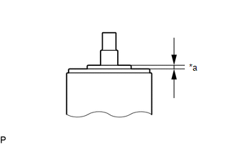
| (d) Using a vernier caliper, measure the commutator length. Standard Length: 3.1 mm (0.122 in.) Maximum Length: 3.8 mm (0.150 in.) If the length is greater than the maximum, replace the starter armature assembly. |
|
3. INSPECT STARTER COMMUTATOR END FRAME ASSEMBLY
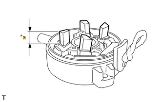
| (a) Check the brush length. (1) Using a vernier caliper, measure the brush length. Standard Length: 9.0 mm (0.354 in.) Minimum Length: 4.0 mm (0.157 in.) If the length is less than the minimum, replace the starter commutator end frame assembly. |
|
| (b) Check the brush insulation. (1) Measure the resistance according to the value(s) in the table below. Standard Resistance:
If the result is not as specified, replace the starter commutator end frame assembly. |
|
4. INSPECT STARTER CLUTCH
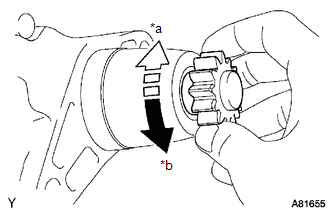
| *a | Lock |
| *b | Free |
(a) Check the clutch pinion gear.
(1) Rotate the clutch pinion gear counterclockwise and check that it turns freely. Try to rotate the clutch pinion gear clockwise and check that it locks.
If the clutch pinion gear does not operate as specified, replace the starter drive housing assembly.
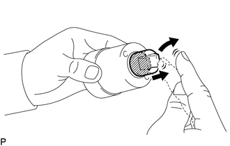
5. INSPECT MAGNET STARTER SWITCH ASSEMBLY
| (a) Check the plunger. (1) Push in the plunger and check that it returns quickly to its original position. If the plunger does not operate as specified, replace the magnet starter switch assembly. |
|
| (b) Check the pull-in coil for an open circuit. (1) Measure the resistance according to the value(s) in the table below. Standard Resistance:
If the result is not as specified, magnet starter switch assembly. |
|
| (c) Check the holding coil for an open circuit. (1) Measure the resistance according to the value(s) in the table below. Standard Resistance:
If the result is not as specified, replace the magnet starter switch assembly. |
|
 Disassembly
DISASSEMBLY PROCEDURE 1. REMOVE MAGNET STARTER SWITCH ASSEMBLY (a) Remove the nut and disconnect the field coil lead wire from terminal C. (b) While holding the magnet starter switch ...
 Installation
INSTALLATION PROCEDURE 1. INSTALL STARTER ASSEMBLY (a) Install the starter assembly with the 2 bolts. Torque: Type A : 46 N·m {469 kgf·cm, 34 ft·lbf} Type B : 37 N·m {377 kgf·cm, 27 ft·lbf ...
Other materials:
Lexus RX (RX 350L, RX450h) 2016-2026 Repair Manual > Fuel Pump Ecu(w/o Rear No. 2 Seat): Components
COMPONENTS ILLUSTRATION *1 DECK BOARD ASSEMBLY *2 FRONT DECK FLOOR BOX *3 REAR DECK FLOOR BOX *4 REAR NO. 4 FLOOR BOARD ILLUSTRATION *1 FUEL PUMP CONTROL ECU ASSEMBLY *2 DECK TRIM SIDE PANEL ASSEMBLY LH N*m (kgf*cm, ft.*lbf): Specified torque - - ...
Lexus RX (RX 350L, RX450h) 2016-2026 Repair Manual > Power Back Door System (w/ Outside Door Control Switch): Power Back Door does not Operate Using Outside Switch
DESCRIPTION The multiplex network door ECU detects the status of the power back door control switch. If the power back door does not operate when the power back door control switch is operated, there may be a malfunction in the power back door control switch circuit. WIRING DIAGRAM CAUTION / NOTICE ...
Lexus RX (RX 350L, RX450h) 2016-{YEAR} Owners Manual
- For your information
- Pictorial index
- For safety and security
- Instrument cluster
- Operation of each component
- Driving
- Lexus Display Audio system
- Interior features
- Maintenance and care
- When trouble arises
- Vehicle specifications
- For owners
Lexus RX (RX 350L, RX450h) 2016-{YEAR} Repair Manual

0.0086