Lexus RX (RX 350L, RX450h) 2016-2026 Repair Manual: Display Disconnected (B15D6)
DESCRIPTION
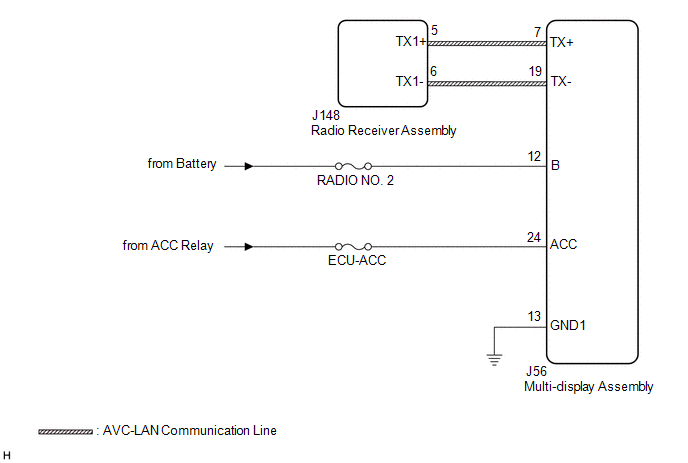
The multi-display assembly and radio receiver assembly are connected by AVC-LAN communication lines.
This DTC is stored when an AVC-LAN communication error occurs between the multi-display assembly and radio receiver assembly.
| DTC No. | Detection Item | DTC Detection Condition | Trouble Area |
|---|---|---|---|
| B15D6 | Display Disconnected | A device that is listed in the AVC-LAN connected device record of the master unit is missing |
|
HINT:
The radio receiver assembly is the master unit.
WIRING DIAGRAM
CAUTION / NOTICE / HINT
NOTICE:
-
Depending on the parts that are replaced during vehicle inspection or maintenance, performing initialization, registration or calibration may be needed. Refer to Precaution for Navigation System.
Click here
.gif)
- Inspect the fuses for circuits related to this system before performing the following procedure.
PROCEDURE
| 1. | CHECK OPTIONAL COMPONENTS (INCLUDING ASSOCIATED WIRING) |
(a) Check for optional components.
(1) Check that optional components (including associated wiring) which generate radio waves are not installed.
| Result | Proceed to |
|---|---|
| Optional components (including associated wiring) are installed. | A |
| Optional components (including associated wiring) are not installed. | B |
HINT:
- Electrical noise from radio waves generated by optional components or the wiring for those components may affect AVC-LAN communication.
- This DTC may be stored when an AVC-LAN communication error occurs due to electrical noise.
| B | .gif) | GO TO STEP 3 |
|
.gif)
| 2. | REMOVE OPTIONAL COMPONENTS (INCLUDING ASSOCIATED WIRING) |
(a) Remove optional components (including associated wiring).
NOTICE:
Do not remove optional components or associated wiring without the permission of the customer.
|
| 3. | CHECK DTC |
(a) Clear the DTCs.
Body Electrical > Navigation System > Clear DTCs(b) Recheck for DTCs and check that no DTCs are output.
Body Electrical > Navigation System > Trouble CodesOK:
No DTCs are output.
| OK | | END |
|
| 4. | CHECK HARNESS AND CONNECTOR (MULTI-DISPLAY ASSEMBLY POWER SOURCE) |
(a) Disconnect the J56 multi-display assembly connector.
(b) Measure the resistance according to the value(s) in the table below.
Standard Resistance:
| Tester Connection | Condition | Specified Condition |
|---|---|---|
| J56-13 (GND1) - Body ground | Always | Below 1 Ω |
(c) Measure the voltage according to the value(s) in the table below.
Standard Voltage:
| Tester Connection | Condition | Specified Condition |
|---|---|---|
| J56-12 (B) - J56-13 (GND1) | Always | 11 to 14 V |
| J56-24 (ACC) - J56-13 (GND1) | Engine switch on (ACC) | 11 to 14 V |
| NG | | REPAIR OR REPLACE HARNESS OR CONNECTOR |
|
| 5. | CHECK HARNESS AND CONNECTOR (RADIO RECEIVER ASSEMBLY - MULTI-DISPLAY ASSEMBLY) |
(a) Disconnect the J148 radio receiver assembly connector.
(b) Disconnect the J56 multi-display assembly connector.
(c) Measure the resistance according to the value(s) in the table below.
Standard Resistance:
| Tester Connection | Condition | Specified Condition |
|---|---|---|
| J148-5 (TX1+) - J56-7 (TX+) | Always | Below 1 Ω |
| J148-6 (TX1-) - J56-19 (TX-) | Always | Below 1 Ω |
| J148-5 (TX1+) or J56-7 (TX+) - Body ground | Always | 10 kΩ or higher |
| J148-6 (TX1-) or J56-19 (TX-) - Body ground | Always | 10 kΩ or higher |
| NG | | REPAIR OR REPLACE HARNESS OR CONNECTOR |
|
| 6. | REPLACE MULTI-DISPLAY ASSEMBLY |
(a) Replace the multi-display assembly with a new or known good one.
Click here
(b) Clear the DTCs.
Body Electrical > Navigation System > Clear DTCs(c) Recheck for DTCs and check that no DTCs are output.
Body Electrical > Navigation System > Trouble CodesOK:
No DTCs are output.
| OK | | END |
| NG | | REPLACE RADIO RECEIVER ASSEMBLY |
 Stereo Component Amplifier Disconnected (B15D3)
DESCRIPTION The radio receiver assembly and stereo component amplifier assembly are connected via MOST communication lines. When a MOST communication error occurs between the radio receiver assembly a ...
 Telematics Transceiver Disconnected (B15DB)
DESCRIPTION If the radio receiver assembly cannot detect the DCM (telematics transceiver) for a certain period of time (90 seconds) after the engine switch is turned on (ACC) and the radio receiver as ...
Other materials:
Lexus RX (RX 350L, RX450h) 2016-2026 Repair Manual > Brake Master Cylinder: Installation
INSTALLATION PROCEDURE 1. INSPECT AND ADJUST BRAKE BOOSTER PUSH ROD Click here 2. INSTALL BRAKE MASTER CYLINDER O-RING (a) Install a new brake master cylinder O-ring to the brake master cylinder sub-assembly. 3. INSTALL BRAKE MASTER CYLINDER SUB-ASSEMBLY WITH WAY NOTICE: When installing a new brak ...
Lexus RX (RX 350L, RX450h) 2016-2026 Repair Manual > Ambient Light (for Instrument Panel): Components
COMPONENTS ILLUSTRATION *1 INSTRUMENT PANEL GARNISH RH *2 INTERIOR ILLUMINATION LIGHT SUB-ASSEMBLY *3 NO. 2 INSTRUMENT CLUSTER MOULDING - - ...
Lexus RX (RX 350L, RX450h) 2016-{YEAR} Owners Manual
- For your information
- Pictorial index
- For safety and security
- Instrument cluster
- Operation of each component
- Driving
- Lexus Display Audio system
- Interior features
- Maintenance and care
- When trouble arises
- Vehicle specifications
- For owners
Lexus RX (RX 350L, RX450h) 2016-{YEAR} Repair Manual

0.011