Lexus RX (RX 350L, RX450h) 2016-2026 Repair Manual: Stereo Component Amplifier Disconnected (B15D3)
DESCRIPTION
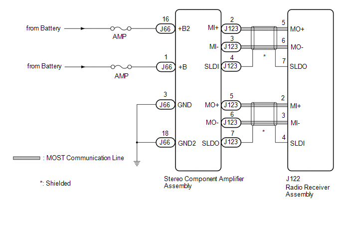
The radio receiver assembly and stereo component amplifier assembly are connected via MOST communication lines.
When a MOST communication error occurs between the radio receiver assembly and stereo component amplifier assembly, this DTC will be stored.
| DTC No. | Detection Item | DTC Detection Condition | Trouble Area |
|---|---|---|---|
| B15D3 | Stereo Component Amplifier Disconnected | A device that is listed in the MOST network connected device record of the master unit is missing. |
|
HINT:
For the MOST network, the radio receiver assembly is the master unit.
WIRING DIAGRAM
CAUTION / NOTICE / HINT
NOTICE:
-
Depending on the parts that are replaced during vehicle inspection or maintenance, performing initialization, registration or calibration may be needed. Refer to Precaution for Navigation System.
Click here
.gif)
- Inspect the fuses for circuits related to this system before performing the following procedure.
PROCEDURE
| 1. | CHECK DTC |
(a) If DTC B15C3 is output, perform troubleshooting for DTC B15C3 first.
| Result | Proceed to |
|---|---|
| DTC B15C3 is not output. | A |
| DTC B15C3 is output. | B |
| B | .gif) | GO TO DTC B15C3 |
|
.gif)
| 2. | CHECK OPTIONAL COMPONENTS (INCLUDING ASSOCIATED WIRING) |
(a) Check that optional components (including associated wiring) which generate radio waves are not installed.
| Result | Proceed to |
|---|---|
| Optional components (including associated wiring) are installed. | A |
| Optional components (including associated wiring) are not installed. | B |
HINT:
- Electrical noise from radio waves generated by optional components or the wiring for those components may affect MOST communication.
- This DTC may be stored when a MOST communication error occurs due to electrical noise.
| B | | GO TO STEP 4 |
|
| 3. | REMOVE OPTIONAL COMPONENTS (INCLUDING ASSOCIATED WIRING) |
(a) Remove optional components (including associated wiring).
NOTICE:
Do not remove optional components or associated wiring without the permission of the customer.
|
| 4. | CHECK DTC |
(a) Clear the DTCs.
Body Electrical > Navigation System > Clear DTCs(b) Recheck for DTCs and check that no DTCs are output.
Body Electrical > Navigation System > Trouble CodesOK:
No DTCs are output.
| OK | | END |
|
| 5. | CHECK HARNESS AND CONNECTOR (STEREO COMPONENT AMPLIFIER ASSEMBLY POWER SOURCE) |
(a) Disconnect the J66 stereo component amplifier assembly connector.
(b) Measure the resistance according to the value(s) in the table below.
Standard Resistance:
| Tester Connection | Condition | Specified Condition |
|---|---|---|
| J66-3 (GND) - Body ground | Always | Below 1 Ω |
| J66-18 (GND2) - Body ground | Always | Below 1 Ω |
(c) Measure the voltage according to the value(s) in the table below.
Standard Voltage:
| Tester Connection | Condition | Specified Condition |
|---|---|---|
| J66-1 (+B) - J66-3 (GND) | Always | 11 to 14 V |
| J66-16 (+B2) - J66-3 (GND) | Always | 11 to 14 V |
| NG | | REPAIR OR REPLACE HARNESS OR CONNECTOR |
|
| 6. | CHECK HARNESS AND CONNECTOR (RADIO RECEIVER ASSEMBLY - STEREO COMPONENT AMPLIFIER ASSEMBLY) |
(a) Disconnect the J122 radio receiver assembly connector.
(b) Disconnect the J123 stereo component amplifier assembly connector.
(c) Measure the resistance according to the value(s) in the table below.
Standard Resistance:
| Tester Connection | Condition | Specified Condition |
|---|---|---|
| J122-5 (MO+) - J123-2 (MI+) | Always | Below 1 Ω |
| J122-6 (MO-) - J123-3 (MI-) | Always | Below 1 Ω |
| J122-7 (SLDO) - J123-4 (SLDI) | Always | Below 1 Ω |
| J122-2 (MI+) - J123-5 (MO+) | Always | Below 1 Ω |
| J122-3 (MI-) - J123-6 (MO-) | Always | Below 1 Ω |
| J122-4 (SLDI) - J123-7 (SLDO) | Always | Below 1 Ω |
| J122-5 (MO+) or J123-2 (MI+) - Body ground | Always | 10 kΩ or higher |
| J122-6 (MO-) or J123-3 (MI-) - Body ground | Always | 10 kΩ or higher |
| J122-7 (SLDO) or J123-4 (SLDI) - Body ground | Always | 10 kΩ or higher |
| J122-2 (MI+) or J123-5 (MO+) - Body ground | Always | 10 kΩ or higher |
| J122-3 (MI-) or J123-6 (MO-) - Body ground | Always | 10 kΩ or higher |
| J122-4 (SLDI) or J123-7 (SLDO) - Body ground | Always | 10 kΩ or higher |
| NG | | REPAIR OR REPLACE HARNESS OR CONNECTOR |
|
| 7. | REPLACE STEREO COMPONENT AMPLIFIER ASSEMBLY |
(a) Replace the stereo component amplifier assembly with a new or known good one.
Click here
(b) Clear the DTCs.
Body Electrical > Navigation System > Clear DTCs(c) Recheck for DTCs and check that no DTCs are output.
Body Electrical > Navigation System > Trouble CodesOK:
No DTCs are output.
| OK | | END |
| NG | | REPLACE RADIO RECEIVER ASSEMBLY |
 MOST Communication Malfunction (B15D0)
DESCRIPTION Navigation system components communicate with each other via MOST communication. If a line short or short to ground occurs in a MOST communication line, communication will not be possible ...
 Display Disconnected (B15D6)
DESCRIPTION The multi-display assembly and radio receiver assembly are connected by AVC-LAN communication lines. This DTC is stored when an AVC-LAN communication error occurs between the multi-display ...
Other materials:
Lexus RX (RX 350L, RX450h) 2016-2026 Repair Manual > Dynamic Torque Control Awd System: Low or High Power Supply Voltage (C1241)
DESCRIPTION If a malfunction in the power source circuit occurs, or a communication malfunction with the skid control ECU (brake actuator assembly) or speed sensor occurs, the 4WD ECU assembly prohibits operation. DTC No. Detection Item DTC Detection Condition Trouble Area C1241 Low o ...
Lexus RX (RX 350L, RX450h) 2016-2026 Repair Manual > Rear Power Seat Control System(for Third Row): Position Sensor Circuit
DESCRIPTION When a fold seat control ECU receives signals from the fold seat switch assembly or No. 1 fold seat switch assembly, it operates the reclining motor and lifter motor of its corresponding rear No. 2 power seat. When the reclining motor or lifter motor is operating, the position sensor (Ha ...
Lexus RX (RX 350L, RX450h) 2016-{YEAR} Owners Manual
- For your information
- Pictorial index
- For safety and security
- Instrument cluster
- Operation of each component
- Driving
- Lexus Display Audio system
- Interior features
- Maintenance and care
- When trouble arises
- Vehicle specifications
- For owners
Lexus RX (RX 350L, RX450h) 2016-{YEAR} Repair Manual

0.0165