Lexus RX (RX 350L, RX450h) 2016-2026 Repair Manual: USB Audio System Recognition/Play Error
DESCRIPTION
When a USB device or "iPod" is connected to the USB jack of the No. 1 stereo jack adapter assembly, it must have playable files. The device must also communicate with and be recognized by the radio receiver assembly. This diagnostic procedure is for when a device is not recognized, or files from the device cannot be played normally.
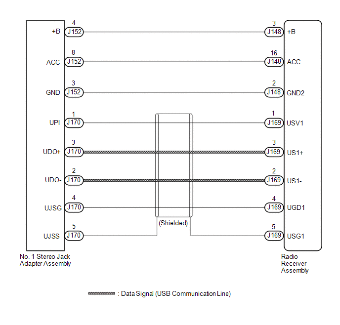
WIRING DIAGRAM
CAUTION / NOTICE / HINT
NOTICE:
Depending on the parts that are replaced during vehicle inspection or maintenance, performing initialization, registration or calibration may be needed. Refer to Precaution for Navigation System.
Click here .gif)
HINT:
- When a large amount of data is in a USB device, it may take a while to begin playback.
- When using a USB device, files that are protected by copyright cannot be played.
-
When files are not played in the sorted order, perform the following procedure before inspection.
- Add numbers in front of the file names.
- Put the files in a folder and copy the folder data to the USB device.
PROCEDURE
| 1. | CHECK USB DEVICE OR "iPod" |
(a) Disconnect the USB device or "iPod" from the No. 1 stereo jack adapter assembly.
(b) Check if playable files are present on the USB device or "iPod".
HINT:
Refer to System Description for playable files.
Click here
(c) Check if the USB device is a compatible format or "iPod" is a compatible version.
HINT:
Refer to System Description for compatible formats and versions.
Click here
| Result | Proceed to |
|---|---|
| No playable files exist, or incompatible device format or version. | A |
| Playable files exist, and compatible device format or version. | B |
| A | .gif) | END (USB DEVICE FORMAT IS INCOMPATIBLE, "iPod" VERSION IS INCOMPATIBLE, OR NO PLAYABLE FILES EXIST) |
|
.gif)
| 2. | CHECK HARNESS AND CONNECTOR (RADIO RECEIVER ASSEMBLY - NO. 1 STEREO JACK ADAPTER ASSEMBLY) |
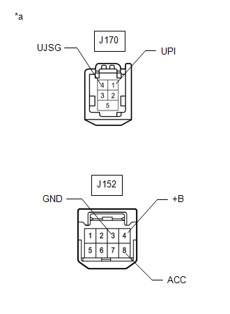
(a) Disconnect the J148 radio receiver assembly connector.
(b) Disconnect the J152 No. 1 stereo jack adapter assembly connector.
(c) Measure the resistance according to the value(s) in the table below.
Standard Resistance:
| Tester Connection | Condition | Specified Condition |
|---|---|---|
| J148-2 (GND2) - J152-3 (GND) | Always | Below 1 Ω |
| J148-3 (+B) - J152-4 (+B) | Always | Below 1 Ω |
| J148-16 (ACC) - J152-8 (ACC) | Always | Below 1 Ω |
| J148-2 (GND2) or J152-3 (GND) - Body ground | Always | 10 kΩ or higher |
| J148-3 (+B) or J152-4 (+B) - Body ground | Always | 10 kΩ or higher |
| J148-16 (ACC) or J152-8 (ACC) - Body ground | Always | 10 kΩ or higher |
| NG | | REPAIR OR REPLACE HARNESS OR CONNECTOR |
|
| 3. | CHECK HARNESS AND CONNECTOR (RADIO RECEIVER ASSEMBLY - NO. 1 STEREO JACK ADAPTER ASSEMBLY) |
| (a) Disconnect the J169 radio receiver assembly connector. |
|
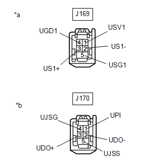
(b) Disconnect the J170 No. 1 stereo jack adapter assembly connector.
(c) Measure the resistance according to the value(s) in the table below.
Standard Resistance:
| Tester Connection | Condition | Specified Condition |
|---|---|---|
| J169-1 (USV1) - J170-1 (UPI) | Always | Below 1 Ω |
| J169-2 (US1-) - J170-2 (UDO-) | Always | Below 1 Ω |
| J169-3 (US1+) - J170-3 (UDO+) | Always | Below 1 Ω |
| J169-4 (UGD1) - J170-4 (UJSG) | Always | Below 1 Ω |
| J169-5 (USG1) - J170-5 (UJSS) | Always | Below 1 Ω |
| J169-1 (USV1) or J170-1 (UPI) - Body ground | Always | 10 kΩ or higher |
| J169-2 (US1-) or J170-2 (UDO-) - Body ground | Always | 10 kΩ or higher |
| J169-3 (US1+) or J170-3 (UDO+) - Body ground | Always | 10 kΩ or higher |
| J169-4 (UGD1) or J170-4 (UJSG) - Body ground | Always | 10 kΩ or higher |
| J169-5 (USG1) or J170-5 (UJSS) - Body ground | Always | 10 kΩ or higher |
| NG | | REPAIR OR REPLACE HARNESS OR CONNECTOR |
|
| 4. | CHECK RADIO RECEIVER ASSEMBLY (NO. 1 STEREO JACK ADAPTER ASSEMBLY POWER SOURCE) |
| (a) Disconnect the J170 and J152 No. 1 stereo jack adapter assembly connectors. |
|
(b) Measure the voltage according to the value(s) in the table below.
Standard Voltage:
| Tester Connection | Condition | Specified Condition |
|---|---|---|
| J170-1 (UPI) - J170-4 (UJSG) | Engine switch on (ACC) | 4.5 to 5.5 V |
| J152-8 (ACC) - J152-3 (GND) | Engine switch on (ACC) | 11 to 14 V |
| J152-4 (+B) - J152-3 (GND) | Always | 11 to 14 V |
| NG | | REPLACE RADIO RECEIVER ASSEMBLY |
|
| 5. | FORMAT USB DEVICE OR RESTORE "iPod" AND RECHECK |
(a) Delete all files in the USB device or "iPod" and format/restore it.
(b) Save the data again and check if it can be played on the in-vehicle device.
NOTICE:
Formatting a USB device or restoring an "iPod" erases all music on the device. Ensure that backup music data is available before performing this operation.
HINT:
Make sure to obtain the customer's permission to perform this procedure.
OK:
Malfunction disappears.
| OK | | END |
|
| 6. | REPLACE USB DEVICE OR "iPod" |
(a) Turn the engine switch off.
HINT:
When this malfunction occurs, it is necessary to turn the engine switch off to make it possible for the vehicle to recognize a new device when it is connected.
(b) Turn the engine switch on (ACC).
(c) Connect a known good USB device or "iPod" to the No. 1 stereo jack adapter assembly.
HINT:
- If the malfunction occurred when a USB device was in use, use another USB device for the inspection. If the malfunction occurred when an "iPod" was in use, use another "iPod" for the inspection.
-
Refer to System Description for compatible formats and versions.
Click here
|
| 7. | CHECK USB DEVICE OR "iPod" |
(a) Check if a USB device or "iPod" is recognized by the radio receiver assembly, and if information such as track, artist and album names is displayed on the screen.
OK:
USB device or "iPod" is recognized properly and the information is displayed on the screen.
| OK | | USB DEVICE OR "iPod" WAS INCOMPATIBLE OR DEFECTIVE |
| NG | | PROCEED TO NEXT SUSPECTED AREA SHOWN IN PROBLEM SYMPTOMS TABLE |
 Portable Player cannot be Registered
CAUTION / NOTICE / HINT HINT: Some versions of "Bluetooth" compatible audio players may not function properly, or the functions may be limited using the radio receiver assembly, even if the portable a ...
 Remote Touch Screen Does not Generate Vibration Feedback
DESCRIPTION When each button displayed on the multi-display assembly is selected via remote touch screen operation, the remote touch screen generates vibration feedback according to communication betw ...
Other materials:
Lexus RX (RX 350L, RX450h) 2016-2026 Repair Manual > Audio And Visual System (for 8 Inch Display): CD cannot be Ejected
CAUTION / NOTICE / HINT NOTICE: Depending on the parts that are replaced during vehicle inspection or maintenance, performing initialization, registration or calibration may be needed. Refer to Precaution for Audio and Visual System. Click here PROCEDURE 1. CHECK OPERATION (a) Press the d ...
Lexus RX (RX 350L, RX450h) 2016-2026 Repair Manual > Thermostat: Removal
REMOVAL CAUTION / NOTICE / HINT The necessary procedures (adjustment, calibration, initialization or registration) that must be performed after parts are removed and installed, or replaced during thermostat removal/installation are shown below. Necessary Procedures After Parts Removed/Installed/Repl ...
Lexus RX (RX 350L, RX450h) 2016-{YEAR} Owners Manual
- For your information
- Pictorial index
- For safety and security
- Instrument cluster
- Operation of each component
- Driving
- Lexus Display Audio system
- Interior features
- Maintenance and care
- When trouble arises
- Vehicle specifications
- For owners
Lexus RX (RX 350L, RX450h) 2016-{YEAR} Repair Manual

0.0099